XQ-58A Valkyrie for 90mm EDF — Build Guide
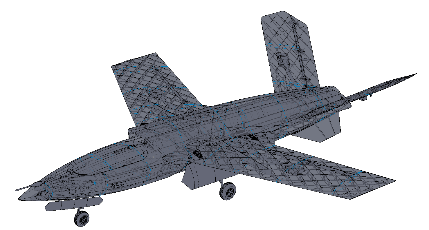
At a glance
- Difficulty: Intermediate to build, advanced to fly
- Wingspan: 1490 mm (58.7")
- Length: 1280 mm (50.4")
- Flying weight: 4650 g (10.3 lb)
Overview
Thank you for purchasing a model by Lofted Aero! 3D printed aircraft are an exciting new segment of the hobby, and we've got no shortage of ideas for new designs. Your support helps us make those reality.
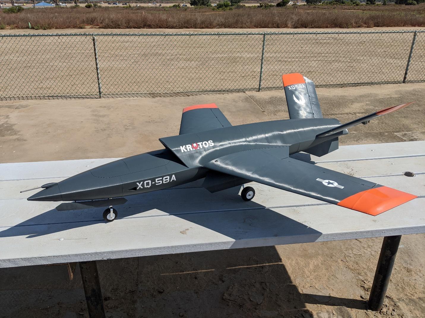
The Valkyrie is inspired by "loyal wingman" concepts and prototypes. These unmanned combat air vehicles are designed to be deployed alongside manned aircraft to protect pilots and assist in their mission. They're fast, stealthy, and capable machines with enough intelligence to operate with little human oversight.
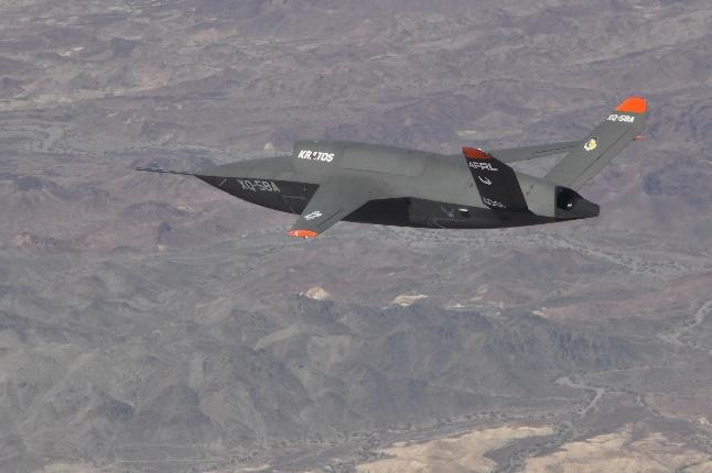
In that spirit, this model can be equipped with an Ardupilot flight controller to enable assisted and autonomous flight features.
Skill meter
Build: While this model is a straightforward configuration to print and assemble, it has numerous complex features such as heat-set threaded inserts and hinged landing gear doors. It's best for builders who have prior experience building 3D printed models.
Flight: This model has smooth handling characteristics but is fast and has a moderate wing loading. It is intended for pilots with prior EDF jet experience.
Specifications
| Spec | Value |
|---|---|
| Wingspan | 1490mm (58.7") |
| Length | 1280mm (50.4") |
| Wing Area | 40.5dm2 (4.36ft2) |
| Print Weight | 2595g |
| Flying Weight | 4650g |
| Wing Loading | 115g/dm2 (37.7oz/ft2) |
| Airfoil | RG-15 modified |
Recommended equipment
The following hardware & electronics are required to complete the Valkyrie. In addition, you'll need some CA glue and activator, your R/C transmitter and receiver, and a LiPo battery charger.
Power system & avionics
| Item | Details |
|---|---|
| Motor & EDF | Changesun 90mm Fan with ~2.5kW Motor |
| ESC | 120A+ ESC |
| Battery | 6S 5000-6000mAh LiPo |
| Flaperon Servos | Hitec HS-85MG (x2) |
| Ruddervator & Nosewheel Servos | Hitec HS-65MG (x3) |
| Landing Gear Door Servos | 9g Metal Gear Servos (x4) |
| Main Retracts | Freewing Type C Retracts (x2) |
| Nose Retract | Freewing Type E Retract |
| Nose Steering Arm | Freewing Steering Arm 5.0mm |
| Gear Sequencer | Lofted Aero Smart Sequencer (or sequencing via R/C radio) |
| Short Servo Extensions | 30cm Servo Extension |
| Medium Servo Extensions | 60cm Servo Extension |
| Long Servo Extensions | 100cm Servo Extension |
| Motor & Battery Leads | 12AWG Silicone Wire |
Autopilot equipment (Optional)
| Item | Details |
|---|---|
| Flight Controller | Matek H743-Wing |
| GPS Receiver | Matek M10Q GPS with Compass |
| Airspeed Sensor | Matek Digital Airspeed Sensor |
Filament
Good filament matters more here than on most prints. The materials below have been tested with our filament and process settings and produce good results.
| Use | Filament | Amount |
|---|---|---|
| PLAStructure, accessories, and thin-wall airframes. | 3DLabPrint PolyAir or eSun PLA+ or Bambu PLA Tough+ | ~2,524 g |
| Foaming TPUTires and flexible parts. | 3DLabPrint FlexiLight or ColorFabb VarioShore TPU | ~86 g |
Hardware
| Item | Part |
|---|---|
| Wing Tube | 10mm x 8mm x 1000mm Carbon Fiber Tube |
| Gear Door Hinge Rods | 2mm Solid Carbon Rod |
| Hinge Pins | 2.5mm x 43mm Hinge Points (x12 - 3 packs) |
| Main Gear Struts | 130mm Oleo Strut (1 pair) |
| Nose Gear Strut | 108mm Offset Strut |
| Axle Rod | 4mm Steel Rod |
| Shaft Collars | 4mm or 3/16" Wheel Collar (1 pack) |
| Pushrods | K&S 1.2mm Piano Wire |
| Pushrod Stoppers (optional) | Pushrod Stoppers |
| Short Threaded Inserts | M3 Short Insert (x10, pack contains 100) |
| Long Threaded Inserts | M3 Long Insert (x18, pack contains 100) |
| Retract & Hatch Mount Screws | M3x6 Flat Head (x16) |
| Servo Hatch Screws | Small Self-Tapping (servo screws, x16) |
| Fan and Cover Mount Screws | M3x6 Socket Head (x9) |
| Stabilizer Mount Screws | M3x16 Socket Head (x2) |
| Aft Wing Mount Screws | M3x20 Flat Head (x2) |
| Forward Wing Mount Screws | M3x30 Socket Head (x2) |
A convenient hardware pack containing all inserts and fasteners is available from Lofted Aero HERE.
Printing thin-wall models
Desktop 3D printers are perfectly capable of producing great-flying R/C models durable enough to withstand hangar rash and general use. However, aircraft designs contain a unique mix of thin surfaces and intricate solid supports that require some practice to print perfectly. Keep the following tips in mind when printing your model.
Slicing the project files
The model download includes .3MF project files for both Bambu Studio and OrcaSlicer – modern, free, and open source slicers with wide support for popular printers and the ability to utilize multiple plates and varying settings within a single project. These project files include print settings tailored to the model as well as filament settings with adjusted temperature and retractions. The provided settings have been tested to suit a wide range of printers – in most cases, no changes should be necessary aside from choosing your printer.
Open the folder for the slicer you're running. The two sets are equivalent and the workflow is the same in both, but each is written in its own slicer's settings dialect, so they aren't interchangeable.
The process and filament presets these projects use are our own. You don't need them to print – the project files already carry the settings – but importing them once from the Print Settings page keeps them in your slicer for future projects, and that page explains what each one is for.
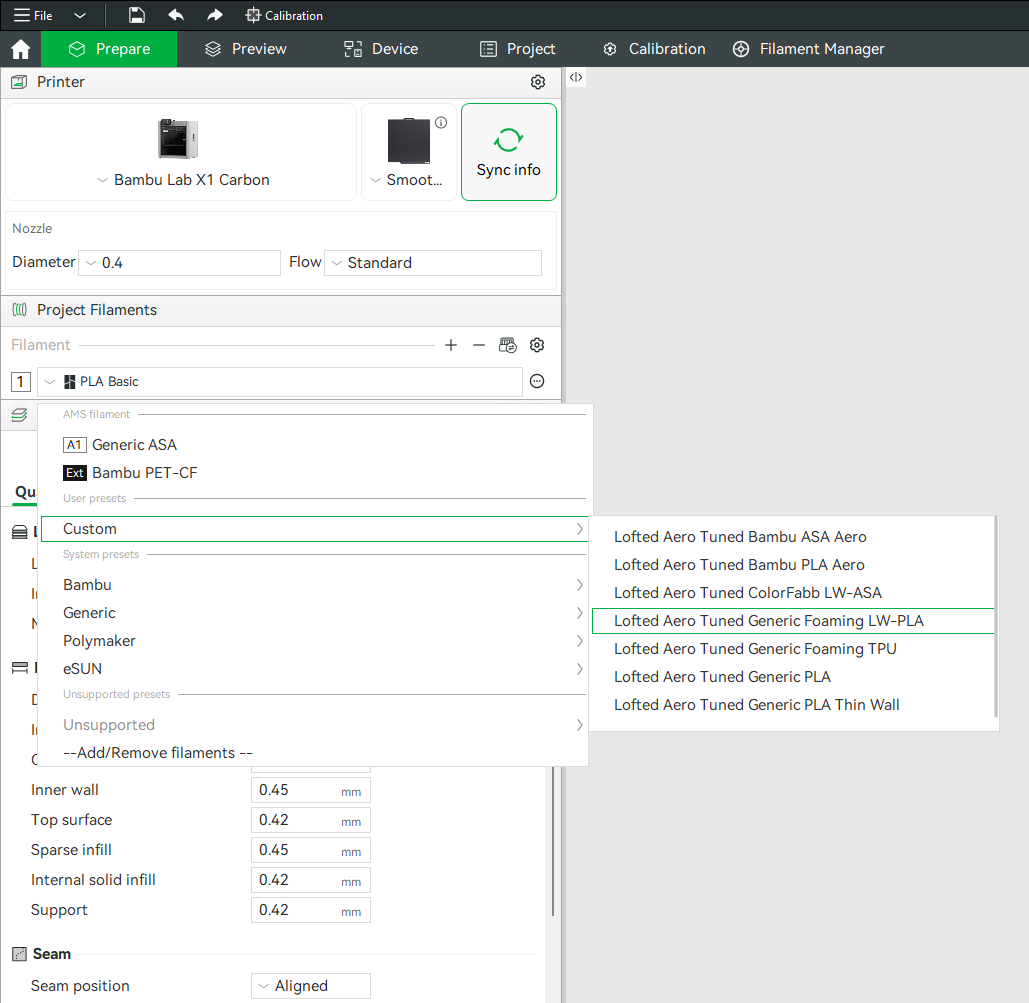
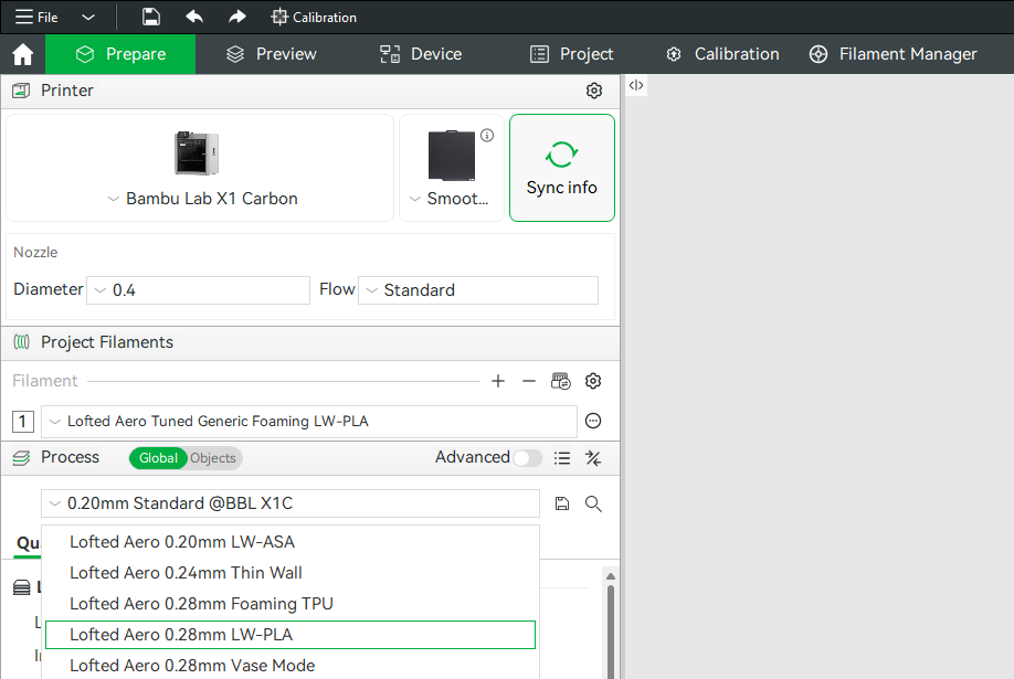
Generic example screenshots
These happen to show the LW-PLA profiles being picked. The profiles this model uses are listed just below.
Profiles used by this model
| Project file | Process profile | Filament profile |
|---|---|---|
| Fuselage · Tail · Wings | Lofted Aero 0.24mm Thin WallBambu Studio OrcaSlicer | Lofted Aero Tuned Generic PLA Thin WallBambu Studio OrcaSlicer |
| Tires | Lofted Aero 0.28mm Foaming TPUBambu Studio OrcaSlicer | Lofted Aero Tuned Generic Foaming TPUBambu Studio OrcaSlicer |
| Accessories | Your slicer's own 0.20mm Standard |
Lofted Aero Tuned Generic PLABambu Studio OrcaSlicer |
Hardware parts like latches, trays, mounts and gear ride your slicer's own stock profile, which is already matched to your printer.
Modifiers and per-object settings
Both slicers allow per-object modifications to slicing settings, and this method is used heavily in the provided .3MF files. Where a part needs extra perimeters, different infill, or a relocated seam, that's applied as a per-object modifier on top of the profile rather than as a separate profile. When making settings changes, be mindful of these per-object settings as well as any other modifiers applied to each part. Switch the Process panel from Global to Objects to see every part in the project, the settings overridden on it, and any modifier volumes attached to it.
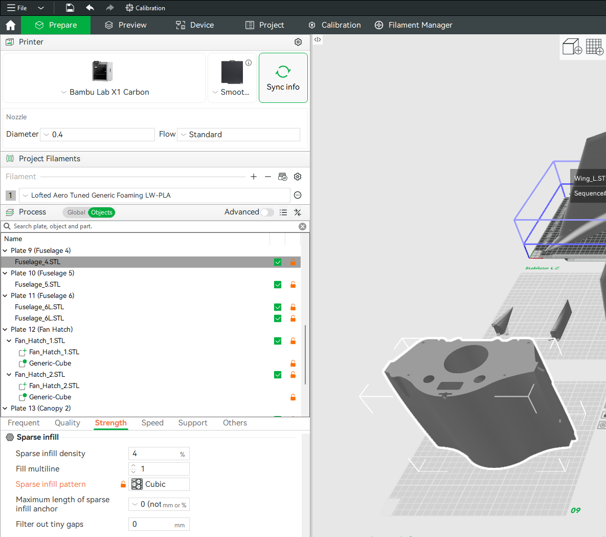
(example screenshot shown – may not represent this model)
Mirrored parts
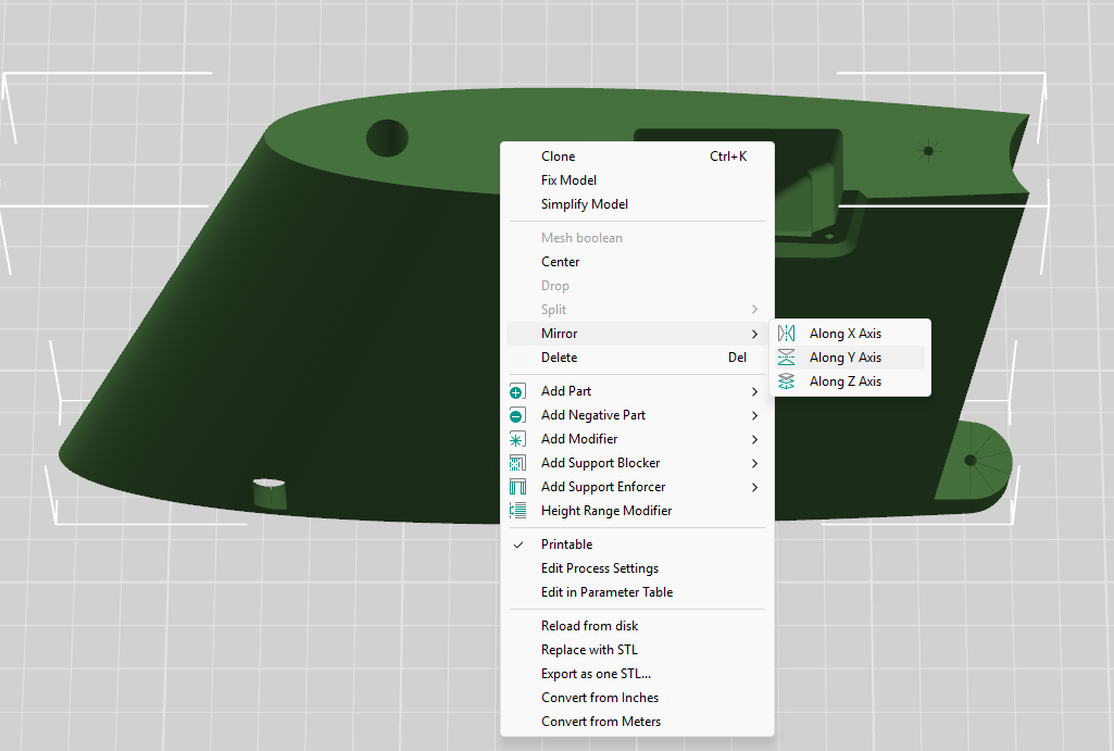
You'll notice that the included STL files often contain parts for only one side of symmetrical components like wings, tail surfaces, and landing gear. Don't worry – you can simply mirror these parts in your slicer to produce the other side. When using the included .3MF project files, this mirroring has already been done.
Other printing options
If you'd rather configure and slice the STL files yourself with the software and method of your choice, refer to the print table below for the profile and modifiers applied to each part.
A few things to keep in mind:
- Retraction should be just enough to prevent stringing between features
- Extra length on restart should be just enough to prevent sparse extrusion at layer start
- Extrusion ratio should be adjusted until print weight equals the suggested part weight
Print table
Reference print profiles, per-part modifiers, and weights for each part.
| Part | Weight | Print Profile | Modifiers |
|---|---|---|---|
| Wing | |||
| Wing L1 | 116g | Lofted Aero 0.24mm Thin Wall0.24mm Height 0.45mm Extrusion Width 1 Perimeter 0 Top / 0 Bottom Layers Cross Hatch @ 0% Back Seam Classic Wall Generator 205°C Nozzle / 60°C Bed |
— |
| Wing R1 | 116g | ||
| Wing LR2 | 70g (35g each) | ||
| Wing LR3 | 112g (56g each) | ||
| Wing LR4 | 94g (47g each) | ||
| Wing LR5 | 50g (25g each) | ||
| Flaperons | 54g (27g per side) | ||
| Flaperon Servo Covers | 10g (5g each) | Your slicer's own 0.20mm Standard0.20mm Height 0.42mm Extrusion Width 2 Perimeters 5 Top / 3 Bottom Layers 15% Infill (Grid in Bambu Studio, Cross Hatch in OrcaSlicer) Aligned Seam Classic Wall Generator 210°C Nozzle / 60°C BedModifiers on every part in this group:0% Fill 4 Top Layers |
— |
| Total Wing | 622g | ||
| Fuselage | |||
| Fuselage 1 | 10g | Lofted Aero 0.24mm Thin Wall0.24mm Height 0.45mm Extrusion Width 1 Perimeter 0 Top / 0 Bottom Layers Cross Hatch @ 0% Back Seam Classic Wall Generator 205°C Nozzle / 60°C Bed |
— |
| Fuselage 2 | 136g | ||
| Fuselage 3 | 98g | ||
| Fuselage 4 | 181g | ||
| Fuselage 5 | 380g | ||
| Fuselage 6 | 146g | ||
| Fuselage 7 | 149g | ||
| Fuselage 8 | 132g | ||
| Fuselage 9 | 84g | ||
| Battery Hatch | 52g | ||
| Avionics Hatch | 41g | ||
| Fan Hatch | 31g | ||
| Fan Cover | 32g |
| |
| Fuselage 1 Pitot (optional) | 10g |
| |
| Hatch Latch | 6g | Your slicer's own 0.20mm Standard0.20mm Height 0.42mm Extrusion Width 2 Perimeters 5 Top / 3 Bottom Layers 15% Infill (Grid in Bambu Studio, Cross Hatch in OrcaSlicer) Aligned Seam Classic Wall Generator 210°C Nozzle / 60°C Bed |
|
| Battery Tray | 35g |
| |
| Pitot Mount (optional) | 5g |
| |
| Total Fuselage | 1528g | ||
| Tail | |||
| Stabilizer LR1 | 54g (27g each) | Lofted Aero 0.24mm Thin Wall0.24mm Height 0.45mm Extrusion Width 1 Perimeter 0 Top / 0 Bottom Layers Cross Hatch @ 0% Back Seam Classic Wall Generator 205°C Nozzle / 60°C Bed |
|
| Stabilizer LR2 | 72g (36g each) | — | |
| Stabilizer LR3 | 54g (27g each) | ||
| Ruddervators | 54g (27g per side) | ||
| Ventral Fins | 26g (13g each) |
| |
| Ruddervator Servo Covers | 8g (4g each) | Your slicer's own 0.20mm Standard0.20mm Height 0.42mm Extrusion Width 2 Perimeters 5 Top / 3 Bottom Layers 15% Infill (Grid in Bambu Studio, Cross Hatch in OrcaSlicer) Aligned Seam Classic Wall Generator 210°C Nozzle / 60°C BedModifiers on every part in this group:0% Fill 4 Top Layers |
— |
| Total Tail | 268g | ||
| Landing Gear | |||
| Nose Gear Doors | 21g | Lofted Aero 0.24mm Thin Wall0.24mm Height 0.45mm Extrusion Width 1 Perimeter 0 Top / 0 Bottom Layers Cross Hatch @ 0% Back Seam Classic Wall Generator 205°C Nozzle / 60°C BedModifiers on every part in this group:5 Top Layers |
— |
| Main Gear Doors 1 | 16g | ||
| Main Gear Doors 2 | 39g | ||
| Wheel Hubs | 26g | Your slicer's own 0.20mm Standard0.20mm Height 0.42mm Extrusion Width 2 Perimeters 5 Top / 3 Bottom Layers 15% Infill (Grid in Bambu Studio, Cross Hatch in OrcaSlicer) Aligned Seam Classic Wall Generator 210°C Nozzle / 60°C BedModifiers on every part in this group:20% Fill 3 Top Layers |
|
| Gear Templates | 4g | — | |
| Main Tire (x2) | 31g each | Lofted Aero 0.28mm Foaming TPU0.28mm Height 0.42mm Extrusion Width 5 Perimeters 8 Top / 8 Bottom Layers Gyroid @ 15% Nearest Seam Arachne Wall Generator 240°C Nozzle / 25°C Bed |
— |
| Nose Tire | 24g |
| |
| Total Landing Gear | 192g | ||
Joining parts
The Valkyrie's printed sections are joined with CA glue (Bob Smith brand works well) and activator. There are a few different types of joints throughout the model.
Base-to-top joint
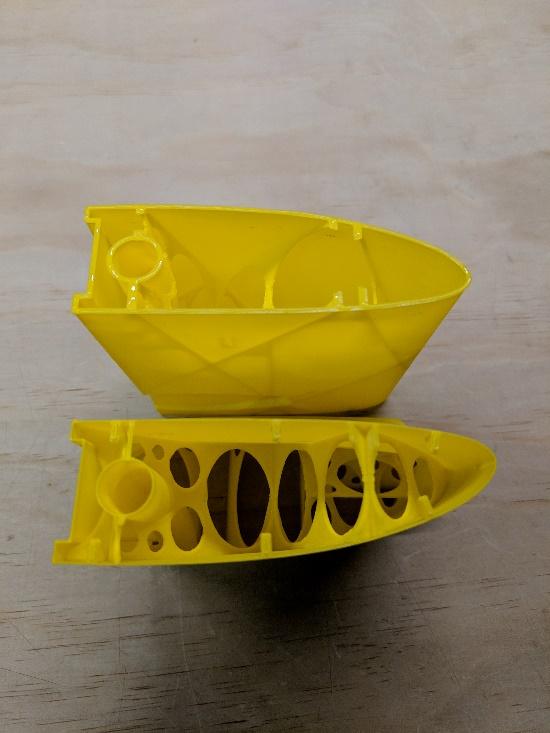
This is the most common type of joint, where the base of one part is glued to the top of another part. There are usually some tabs present to help with alignment. Place a bead of CA along the perimeter and internal edges of the part with the base side, as these edges have a bit more surface area. Then place that part on top of the opposite part, again using gravity to hold the parts together. Verify that the tabs achieved proper alignment and spray CA activator to secure.
Base-to-base joint
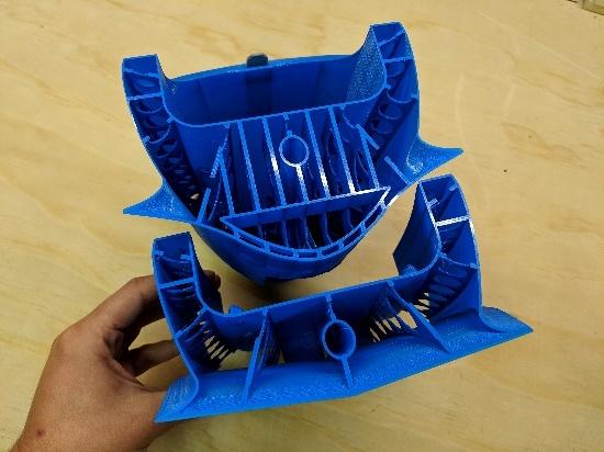
Some parts are joined with their base surfaces facing each other. There are no alignment tabs in this scenario, but the increased surface area helps somewhat. Place a bead of CA along the perimeter and internal edges of one of the parts. Then place that part on top of the opposite part, again using gravity to hold the parts together. Before glue sets, gently nudge the parts to align them. Once satisfied, spray CA activator to secure.
Solid face joint
The joints on parts including control horns often contain solid faces to increase strength. Spread a thin layer of CA on one face and then carefully align with the second. Once satisfied with alignment, spray CA activator to secure. Some control surface parts join solid faces on one side with hollow perimeters on the opposite side. For these, place a bead of glue around the edges of the hollow perimeter and any internal structure, then align it on top of the solid face of the opposite part. When satisfied with alignment, spray CA activator to secure.
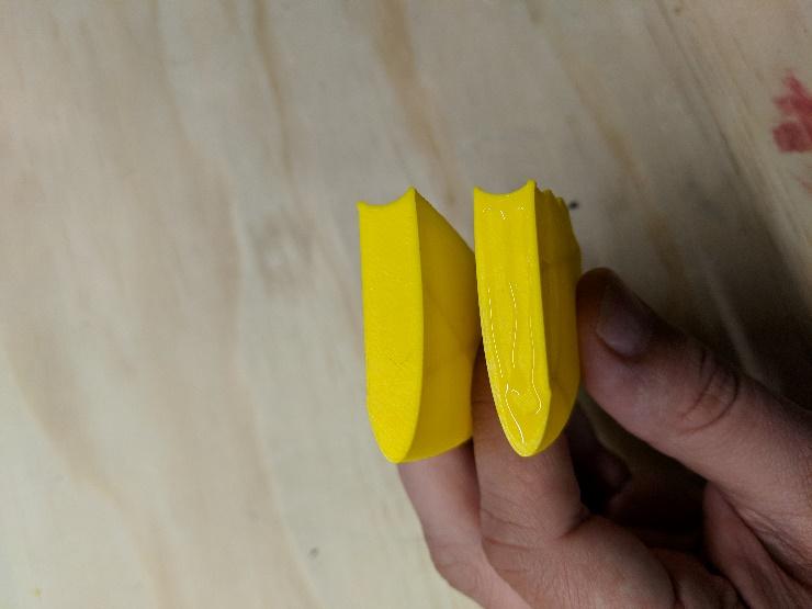
Wing assembly
-
Assemble the flaperons, gluing both sections together at the control horn in the middle.
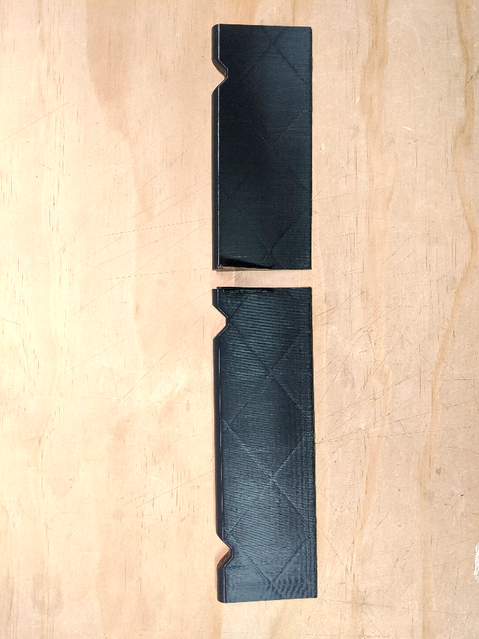
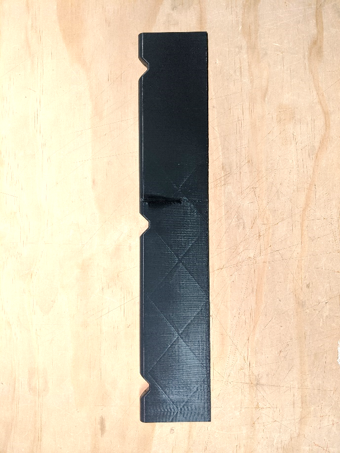
-
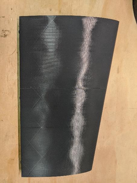
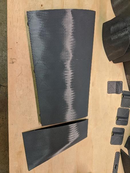
Assemble sections 3 and 4, then glue on the wingtip (section 5)
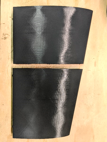
-
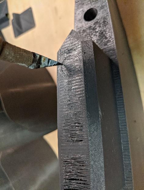
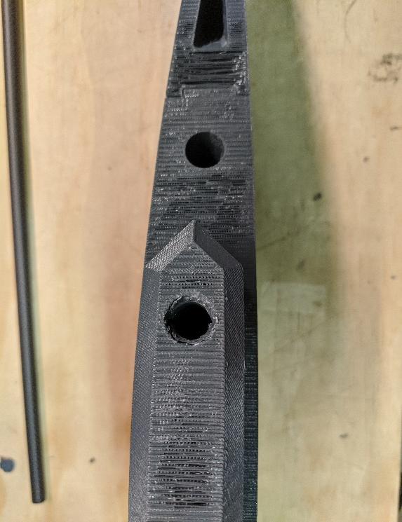
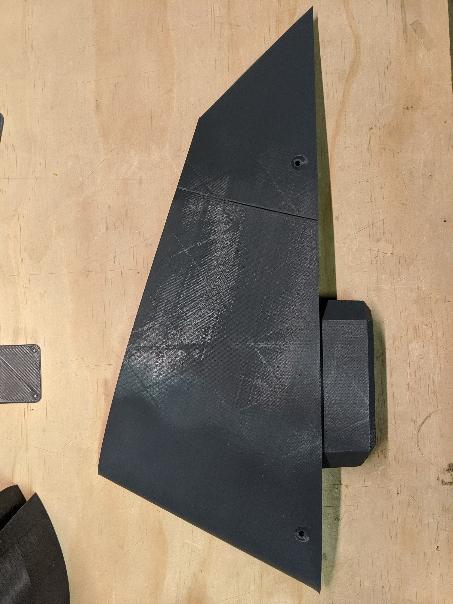
Use a hot knife or soldering iron to remove the plastic covering the spar channel in Wing 1. Then, join wing sections 1 and 2.
-
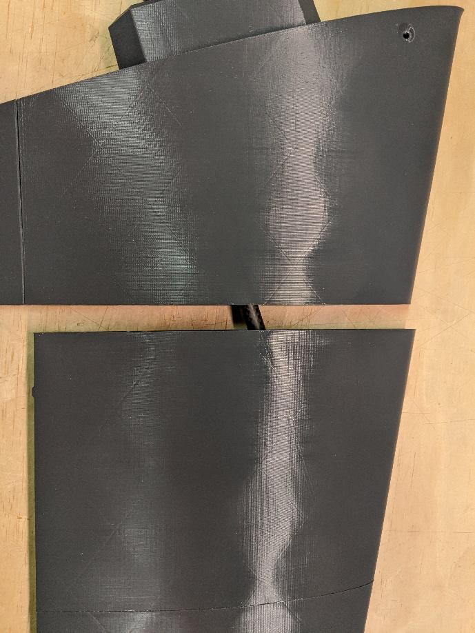
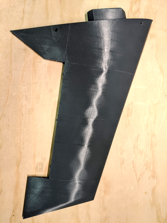
Using the spar tube for alignment, join the assembled sections 1 & 2 with the assembled outer panel.
-
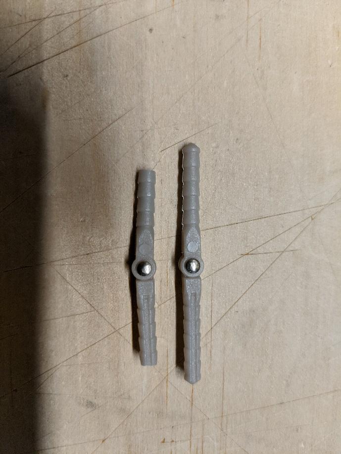
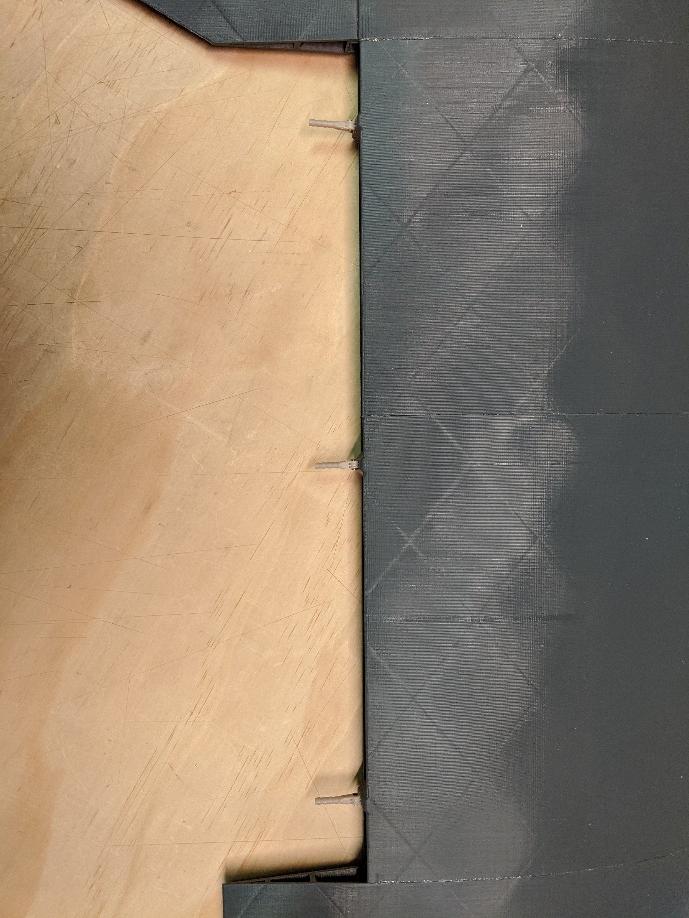
Trim three hinge pins as shown. Place a drop of glue on each pin, then push them into their mount holes in the wings. Be sure that their rotation axes are aligned with the hingeline. Then, use activator to secure.
-
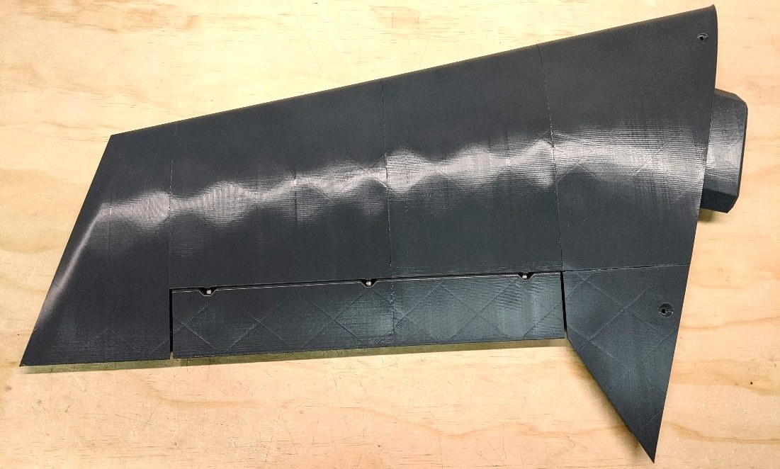
Place a drop of glue on the exposed ends of all three hinge pins and carefully install the flaperon, making sure the hinge pins engage their mount holes. When the flaperon is fully seated, spray CA activator while working the hinge back and forth to make sure the hinge pins stay free.
-
Repeat steps 1-6 with the opposite wing.
Tail assembly
-
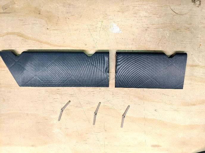
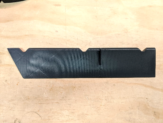
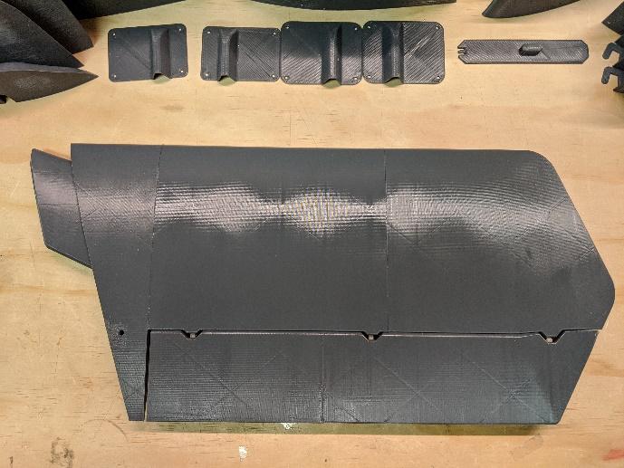
Join the two ruddervator sections at the control horn.
-
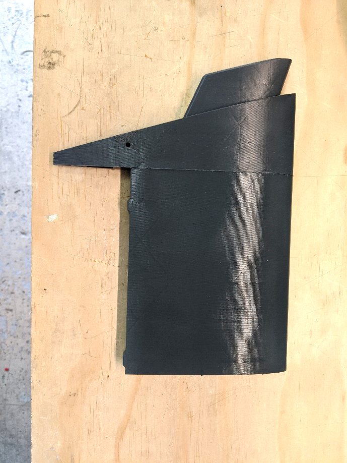
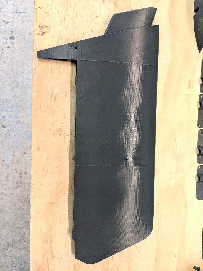
Join stabilizer sections 1 and 2, then join stabilizer section 3.
-
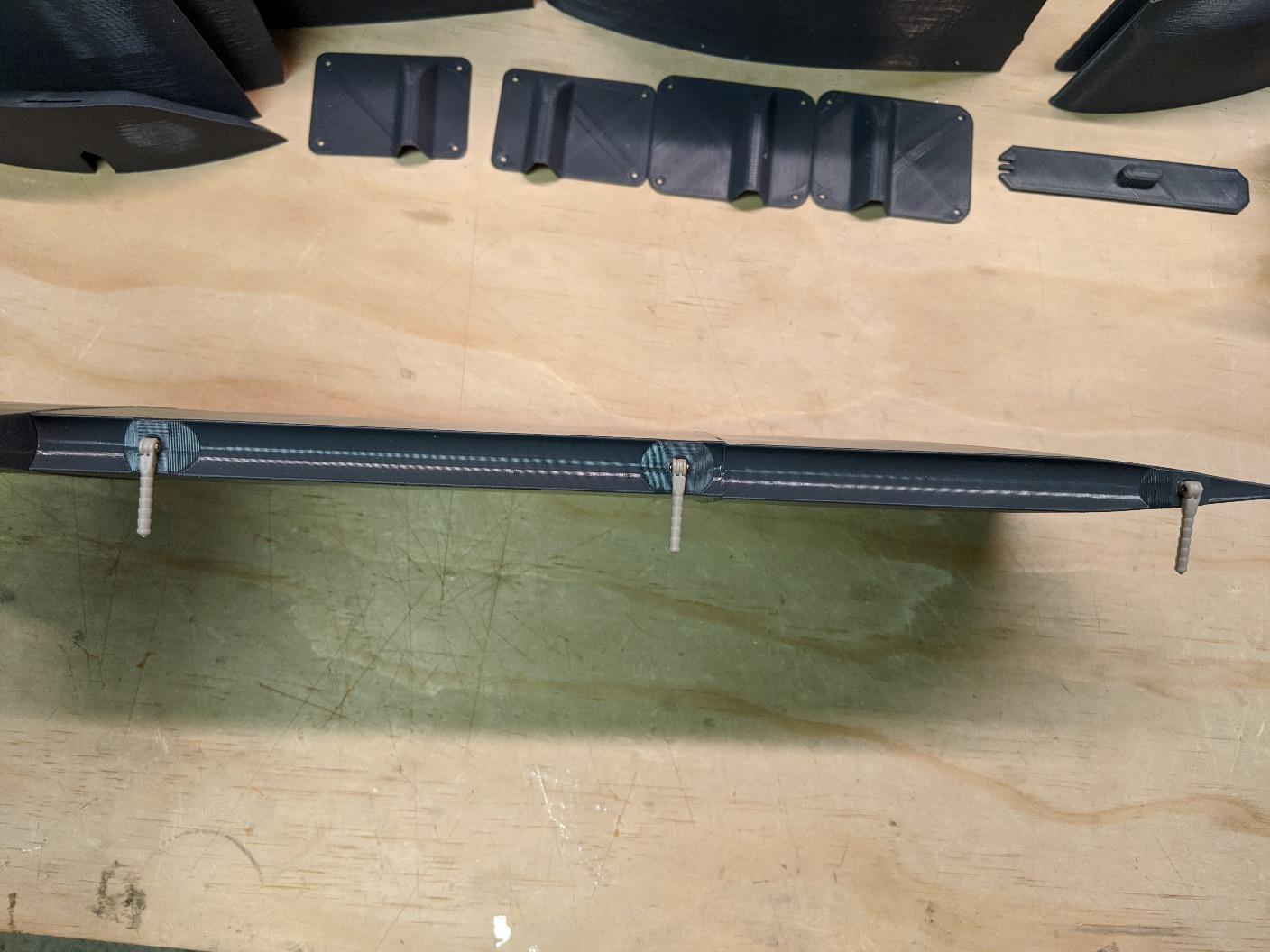
As with the ailerons, place a drop of glue on each of three hinge pins then push them into their mount holes in the stabilizer. Be sure that their rotation axes are aligned with the hingeline. Then, use activator to secure. Note that trimming the hinge pins is not required.
-
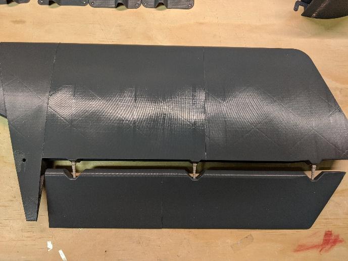
Place a drop of glue on the exposed ends of all three hinge pins and carefully install the ruddervator, making sure the hinge pins engage their mount holes. When the ruddervator is fully seated, spray CA activator while working the hinge back and forth to make sure the hinge pins stay free.
-
Repeat steps 1-4 to complete the opposite stabilizer.
Fuselage assembly
-
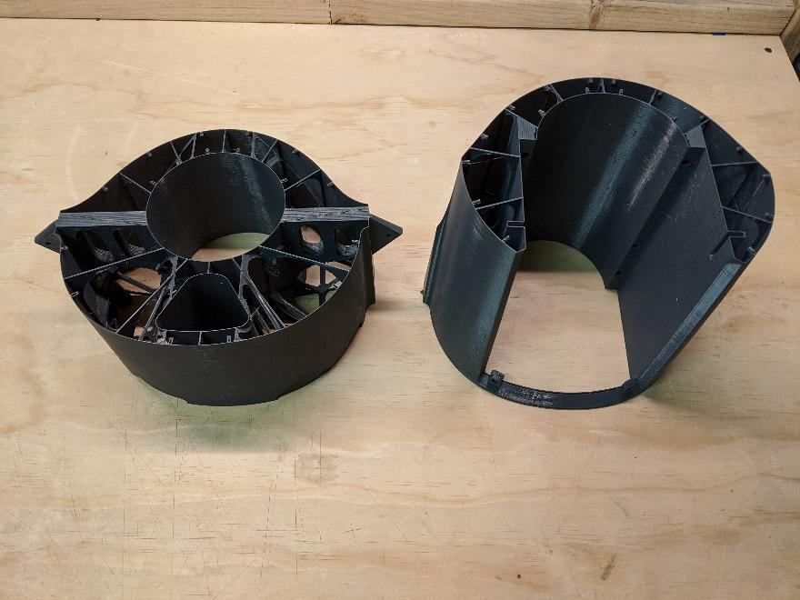
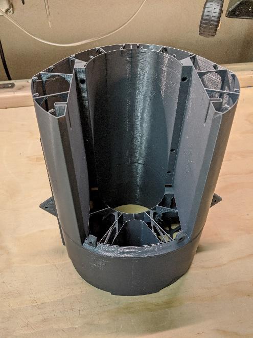
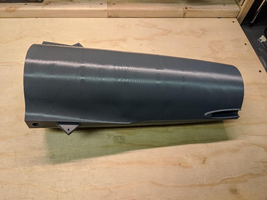
Prepare and join sections 6 and 7 with CA. Be careful to avoid applying glue to surfaces that are not part of the joint. Ensure that the edges are aligned, especially along the fan hatch opening.
-
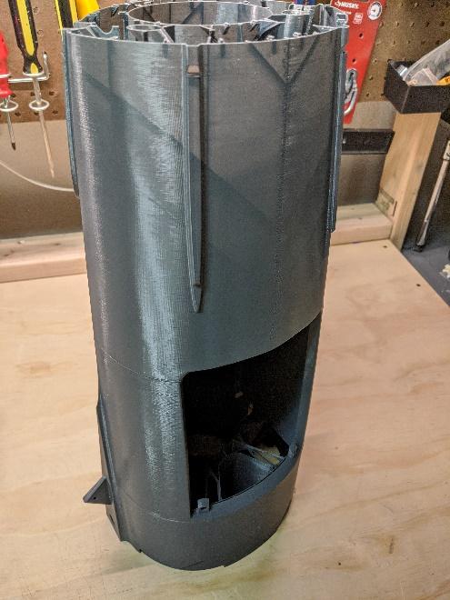
Join section 8 to section 7. Again, be careful to avoid applying glue to surfaces that are not part of the joint.
-
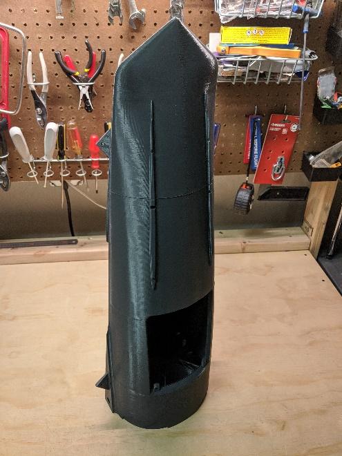
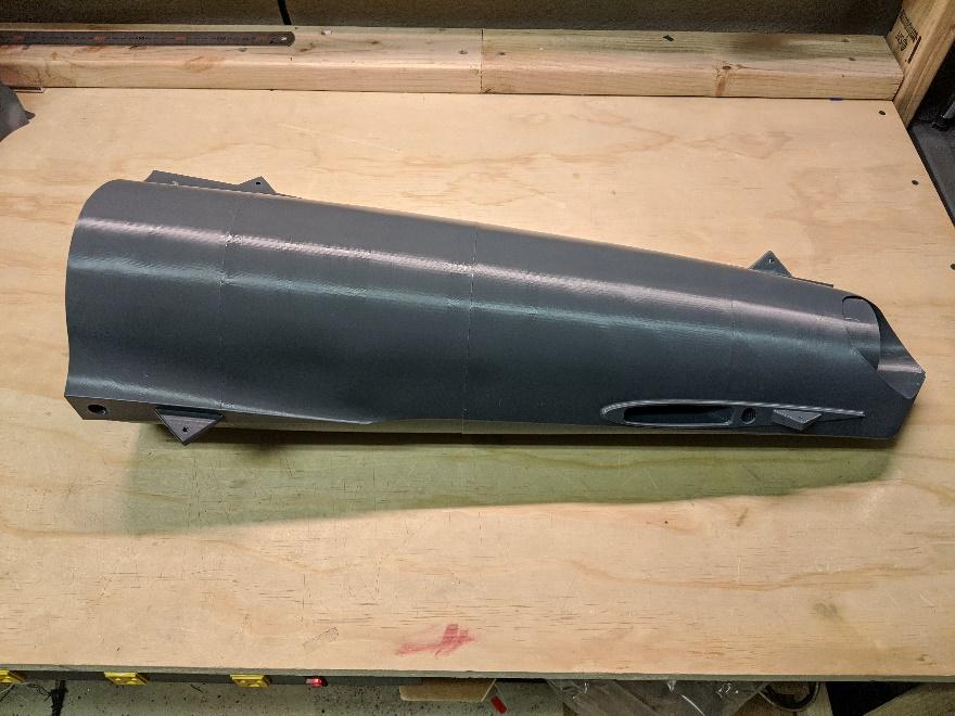
Join section 9 to section 8.
-
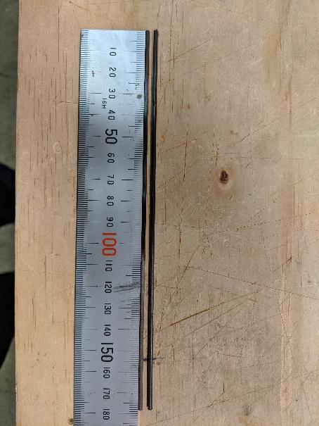
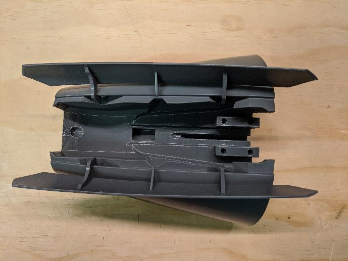
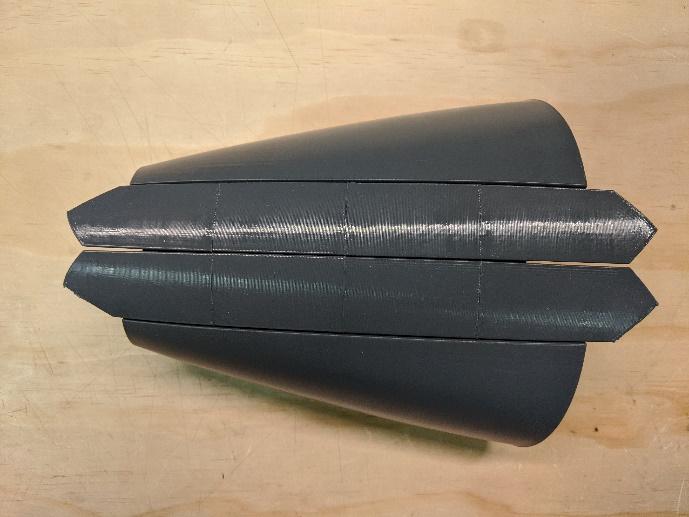
Moving on to the nose, prepare two lengths of the carbon fiber door hinge rods 177mm long. Assemble the nose gear door sections, using the rods to keep them aligned.
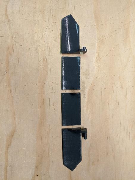
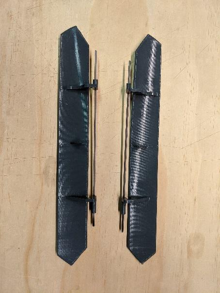
-
Hold the nose gear doors in place in Fuselage 2, then slide the hinge rods into their channels to secure them. Check that the doors move freely and add a drop of CA to fix the rods.
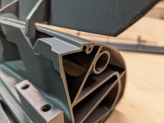
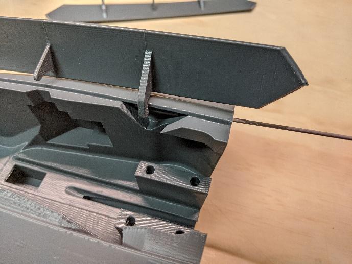
-
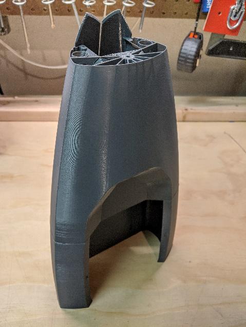
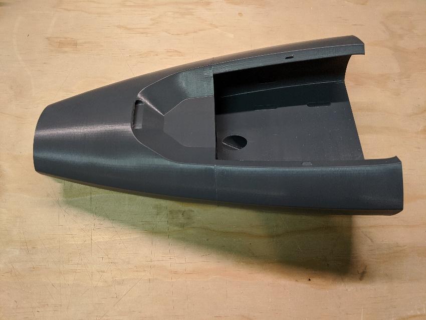
Stack Fuselage 2 on Fuselage 3 and glue with CA. Do not apply glue to surfaces not involved in the joint.
-
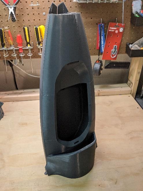
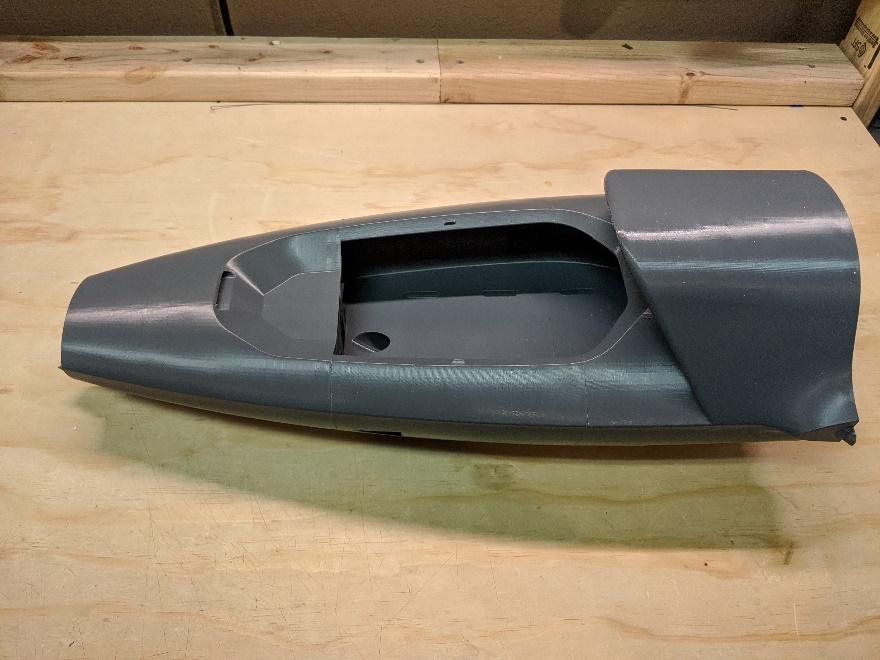
Join fuselage sections 3 and 4.
-
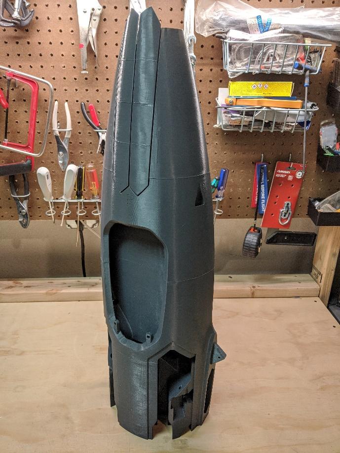
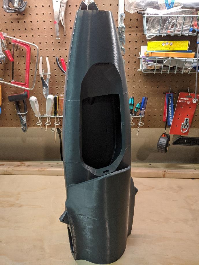
Join fuselage sections 4 and 5.
-
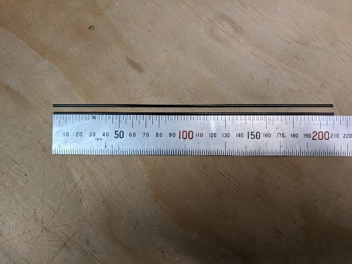
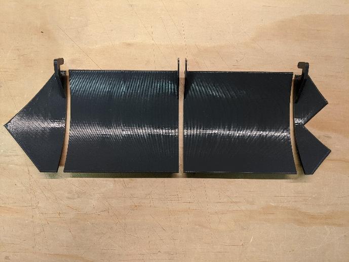
Prepare two lengths of the carbon fiber door hinge rods 210mm long. Assemble the main gear door sections, using the rods to keep them aligned.
-
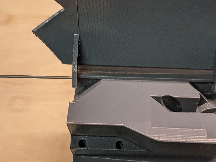
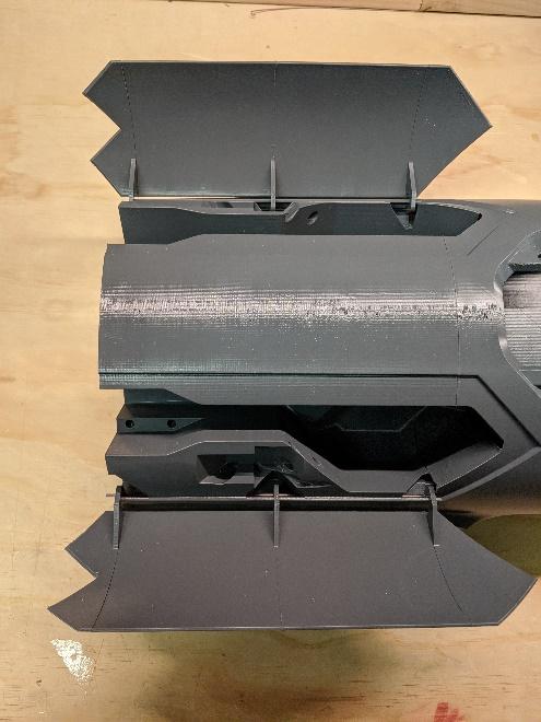
Hold the main gear doors in place in Fuselage 5, then slide the hinge rods into their channels to secure them. Do not glue the carbon rods, which should protrude about 10mm from the rear face of Fuselage 5.
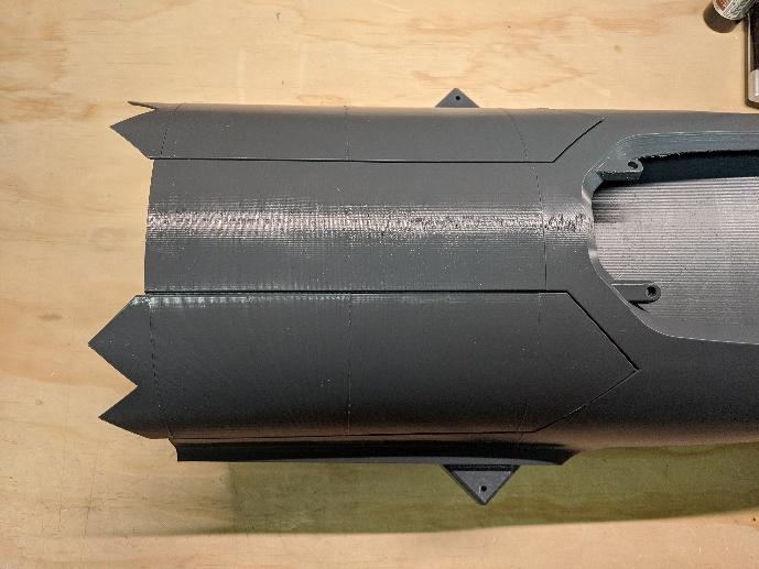
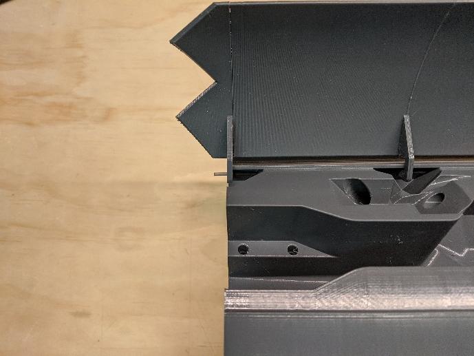
-
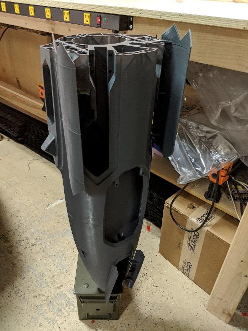
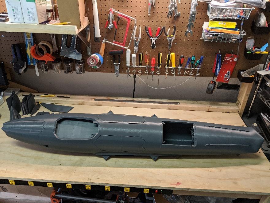
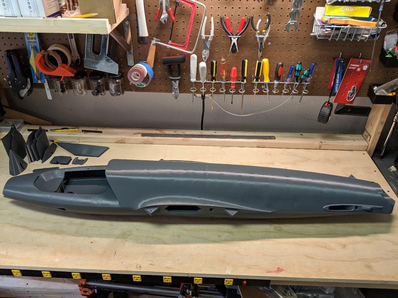
Stand the Fuselage 2-5 stack on its nose using a box or other support to keep the nose gear doors from interfering. Apply CA to the Fuselage 6-9 stack and carefully join the two subassemblies together. Do not apply CA to the carbon fiber landing gear door hinge rods.
-
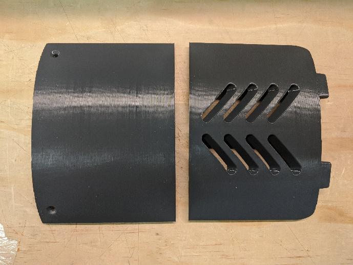
Glue fan hatch sections 1 and 2 together.
-
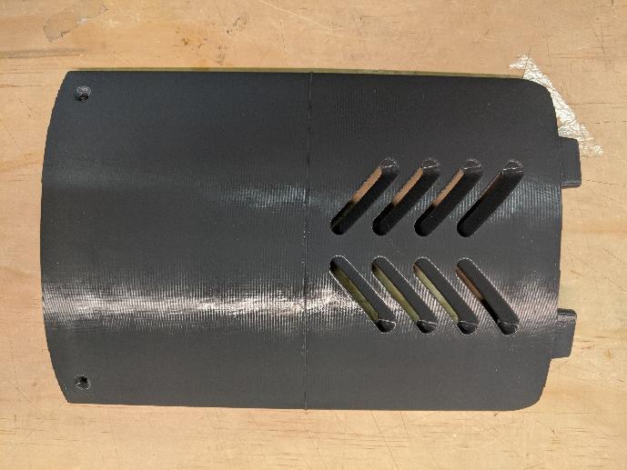
Glue avionics hatch sections 1 and 2 together.
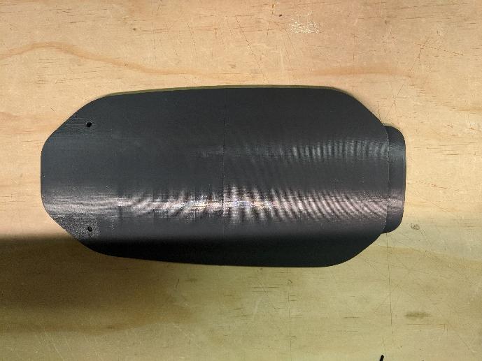
-
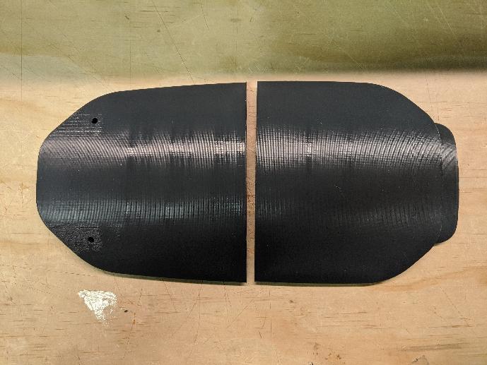
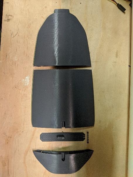
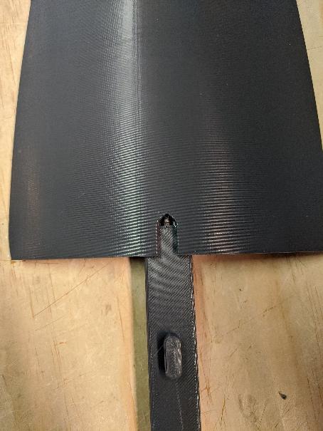
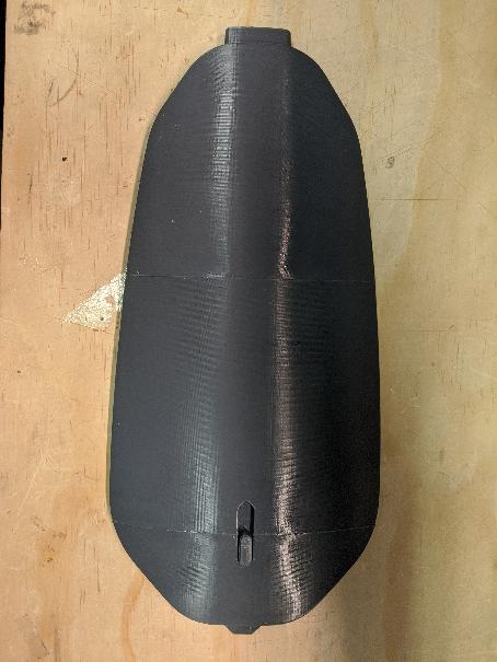
Glue battery hatch sections 1 and 2 together, then insert a pen spring and the hatch latch into section 2. Finally, join section 3 and ensure the hatch latch moves freely.
Threaded inserts
-
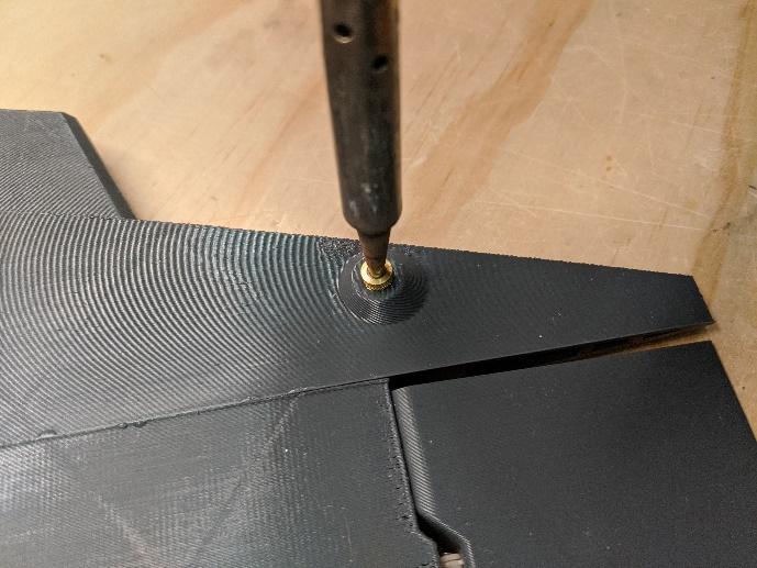
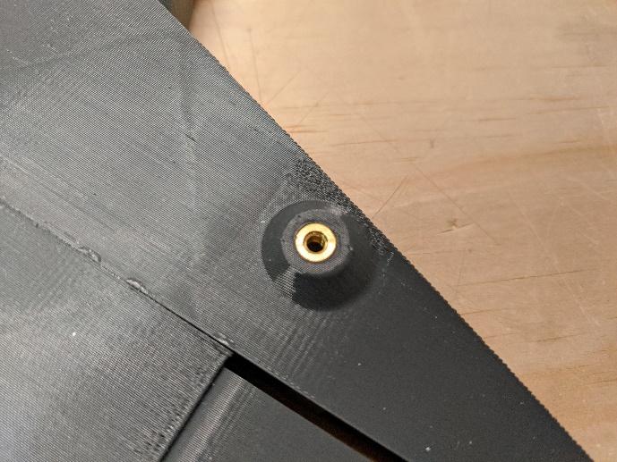
Using a clean soldering iron set to around 385C, install a short M3 threaded insert into the pockets on each stabilizer. Be careful to avoid excess melted plastic oozing into the threads.
-
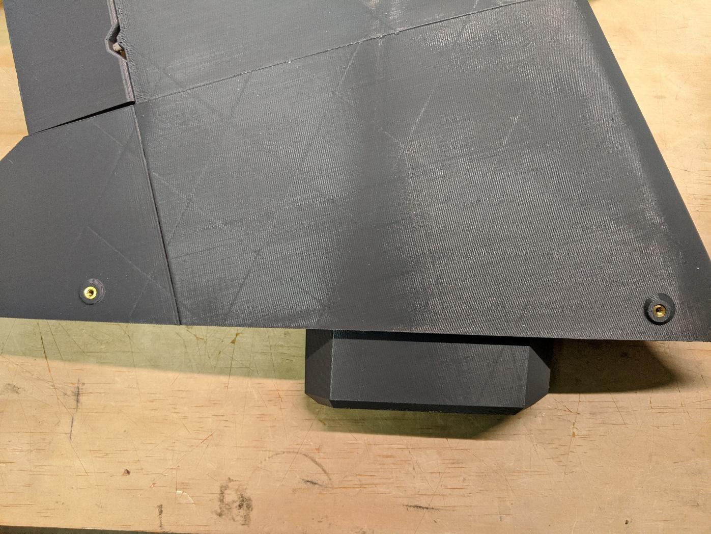
Similarly, install two short M3 threaded inserts into each wing.
-
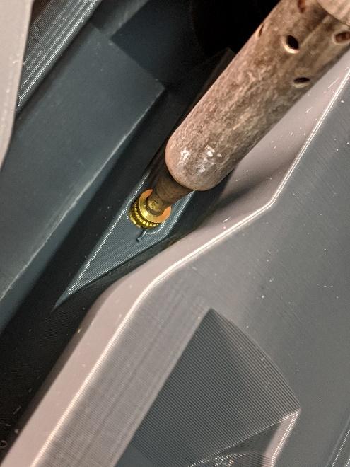
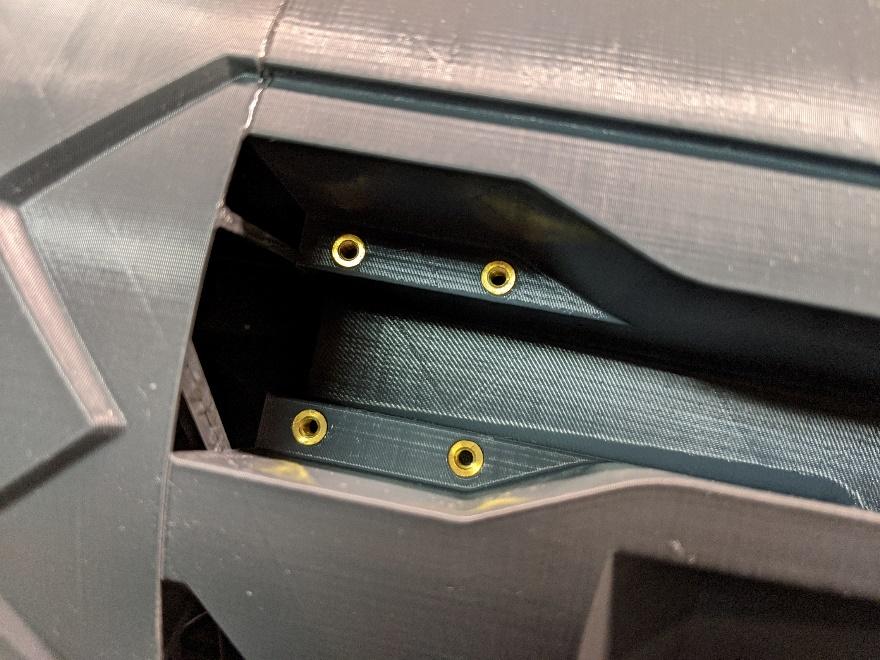
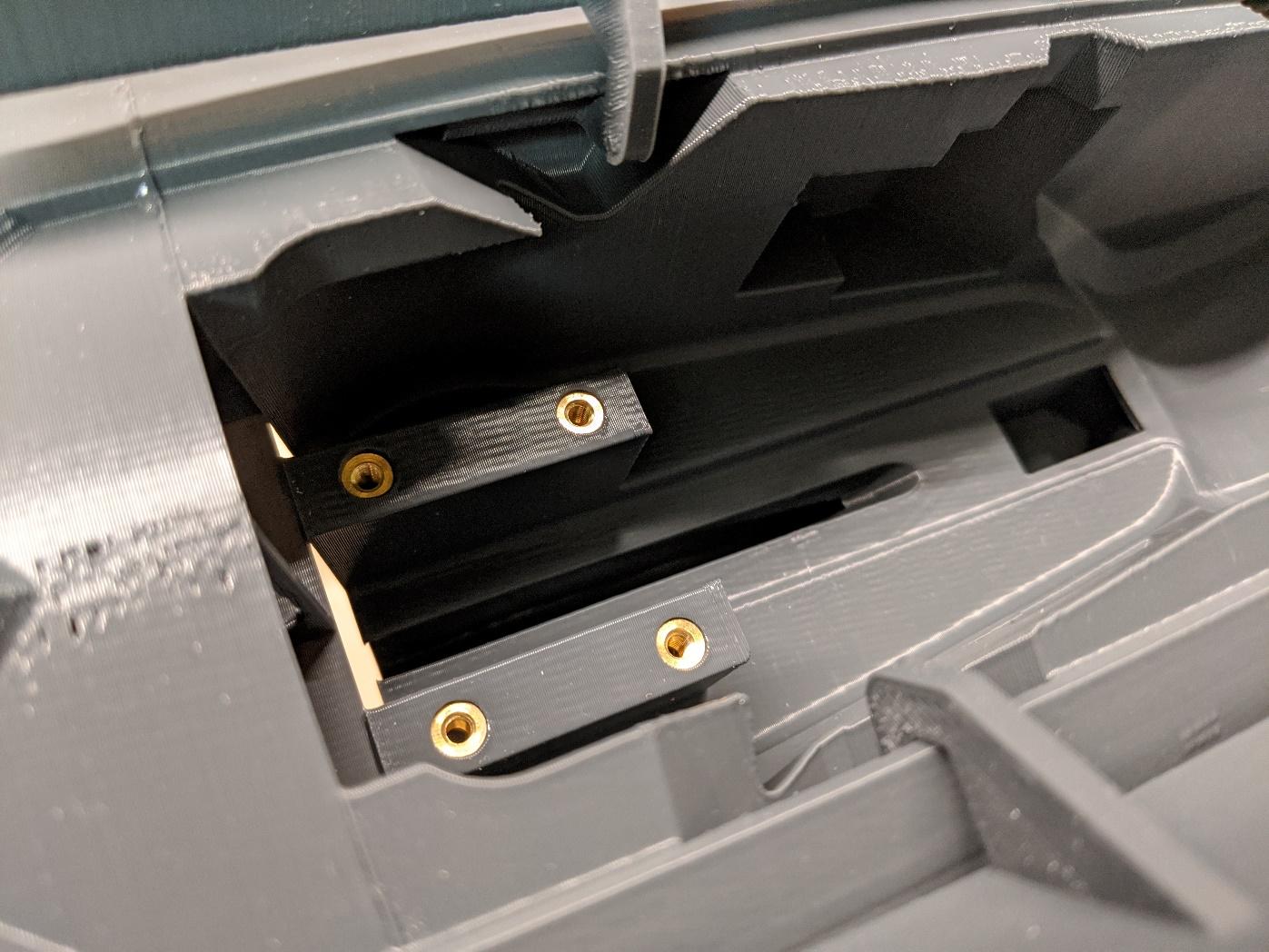
Install four long M3 threaded inserts into the main and nose retract mount locations.
-
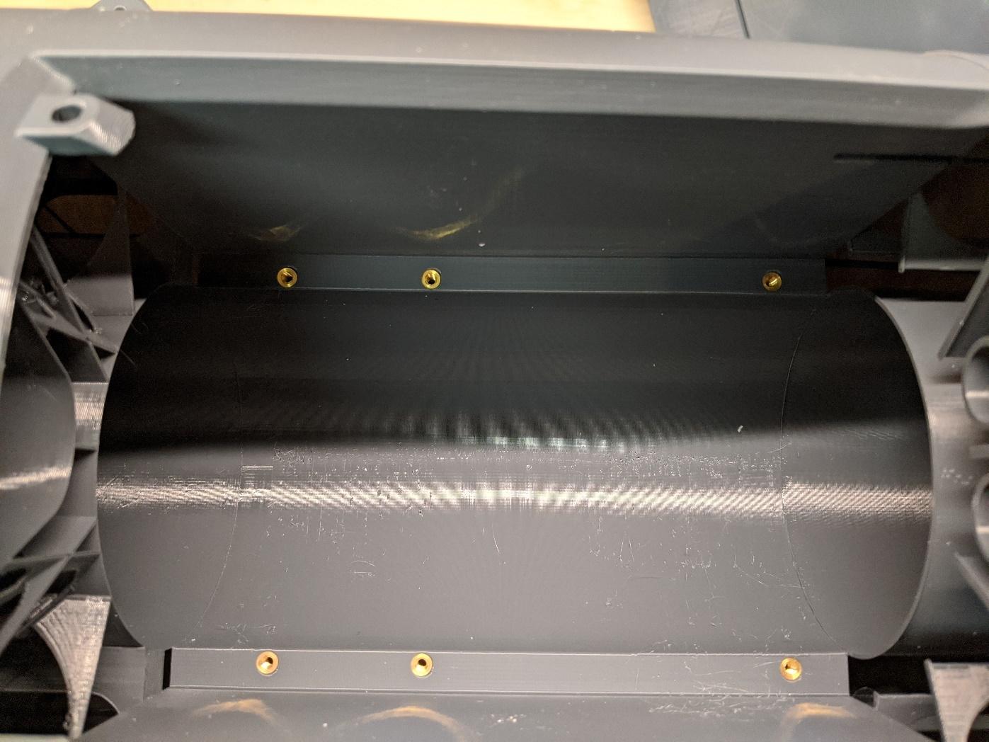
Install six long M3 threaded inserts into the fan mounting area.
-
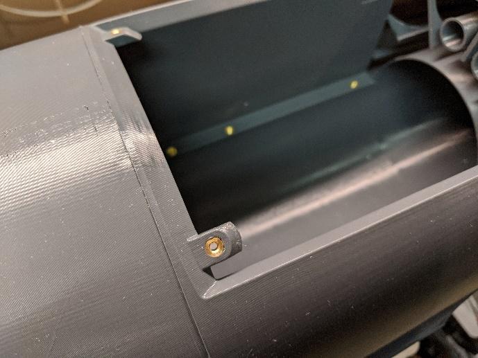
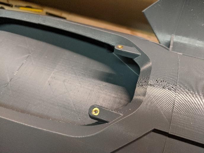
Install two short M3 threaded inserts on the mount tabs for the fan hatch and for the avionics hatch.
Landing gear & retracts
-
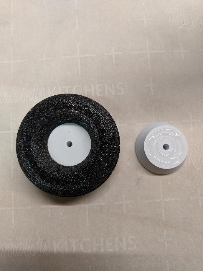
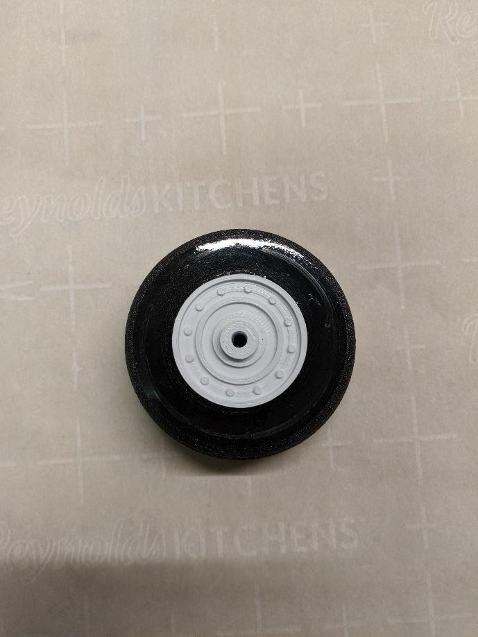
Glue the wheel hub halves together inside the tires.
-
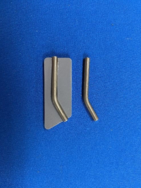
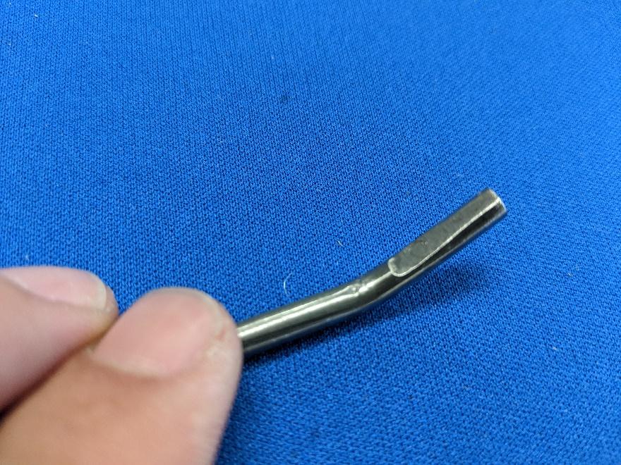
Use a bench vice and a hammer to bend two lengths of 4mm steel rod to conform to the shape of the printed main gear axle template. Grind a flat spot into the short segment as shown.
-
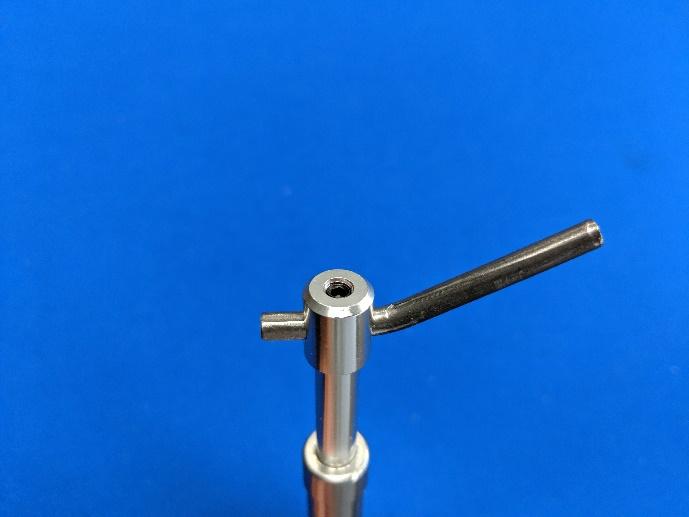
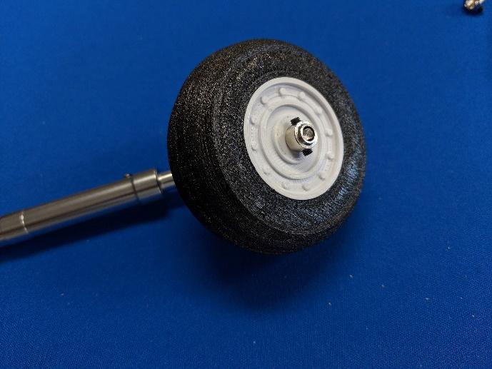
Fix the main gear axles to the main struts with the set screw as shown. Then, install the main wheels using set screw collars.
-
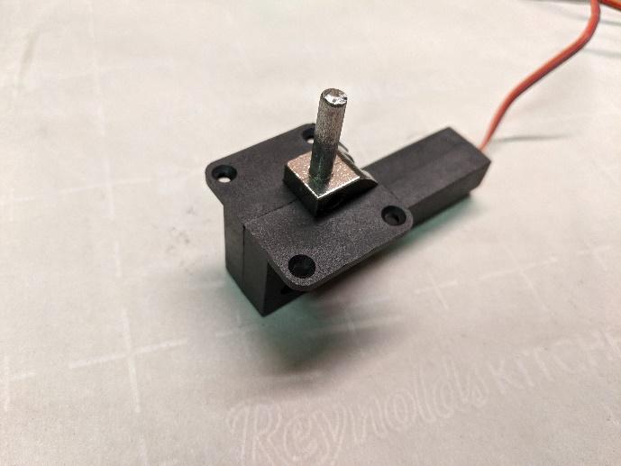
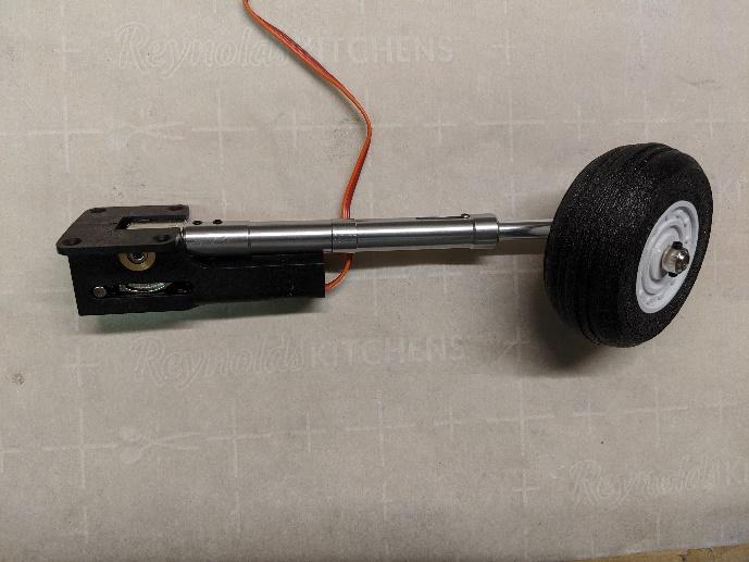
Install the retract pins (or a length of steel rod) into the trunions using set screws. Then, install the main gear struts.
-
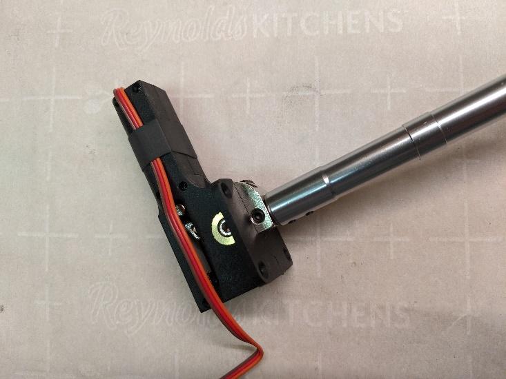
Fold back the leads on the main retracts and secure with a piece of shrink tubing as shown.
-
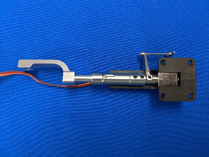
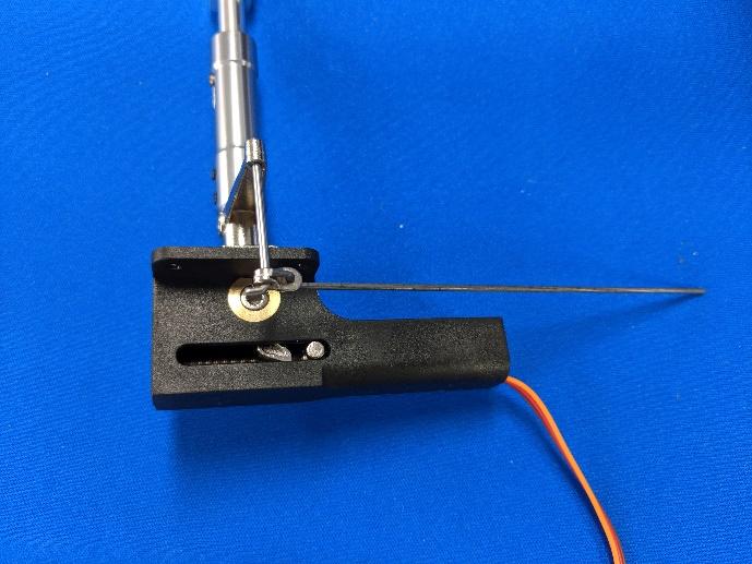
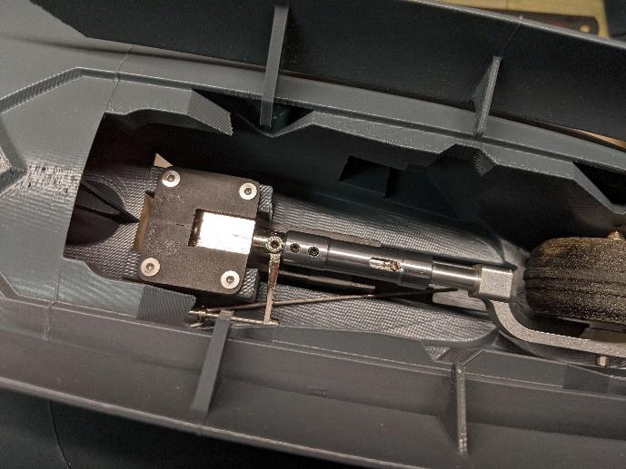
Attach the nose gear strut to the nose retract. Ensure that it can be pivoted freely using the steering arm. Prepare a length of pushrod with a z-bend and insert into the steering arm as shown.
-
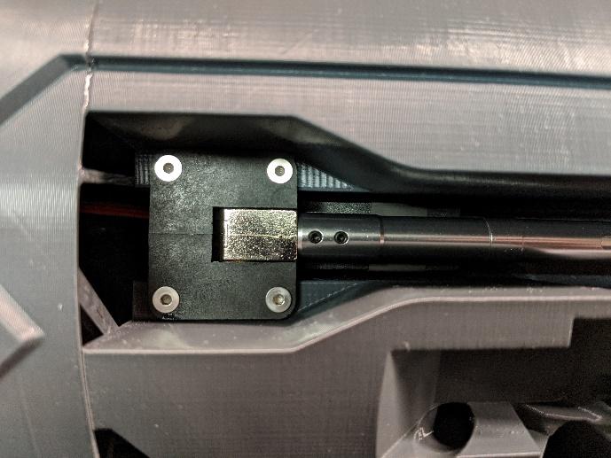
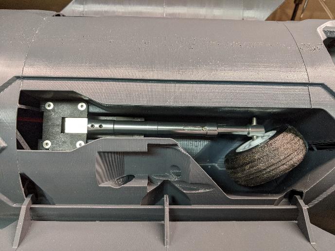
Use four M3 x 6mm flat-head screws to install the main retracts in their mounts. Non-permanent threadlocker is recommended.
-
Similarly, install the nose retract. Attach the nose wheel and axle if not already installed.
Servo installation
-
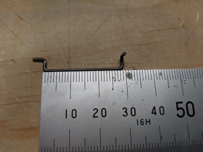
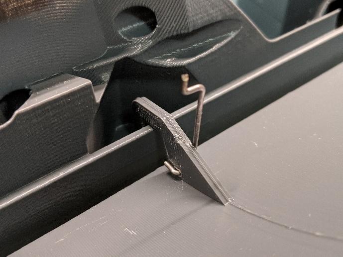
Make two main gear door pushrods from thin wire as shown. They must be mirror images. Use a heated length of wire to clear the hole in the control horn of each gear door, then insert the pushrods.
-
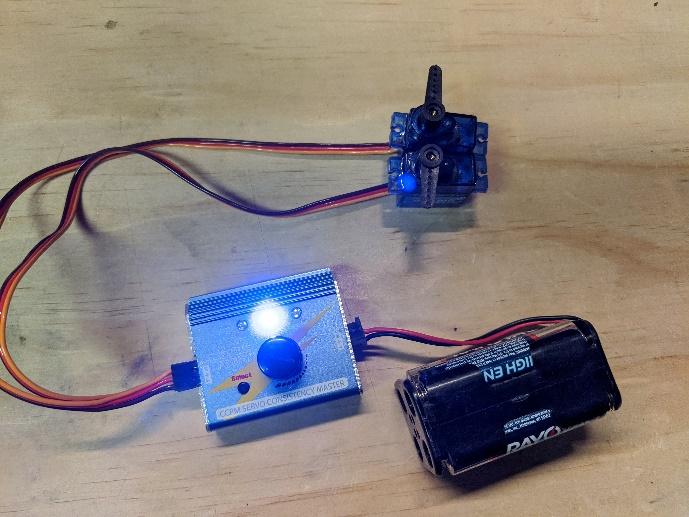
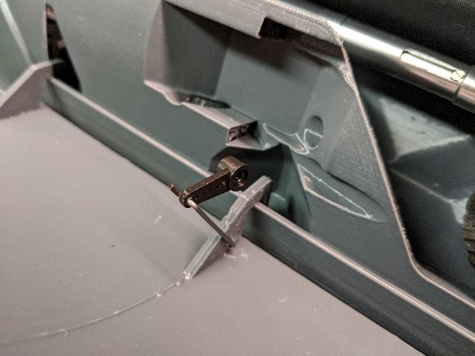
Center the main gear door servos. Install the servo arms onto the main gear door pushrods.
-
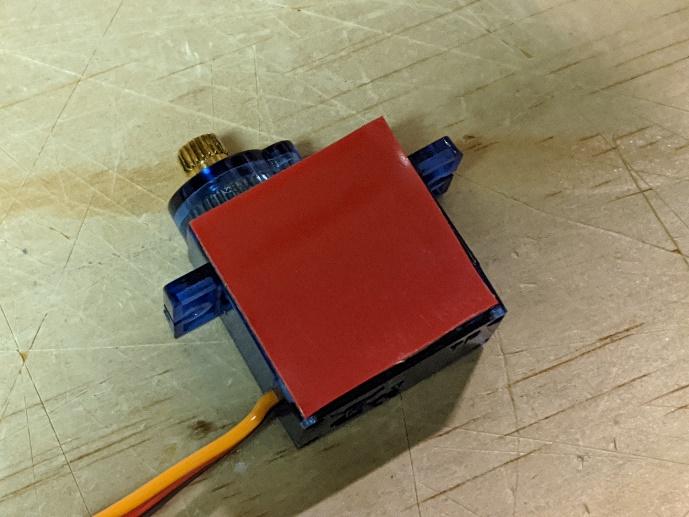
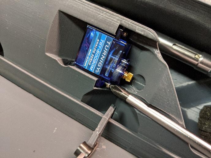
Use double-sided servo tape and screws to install the main gear door servos into their pockets.
-
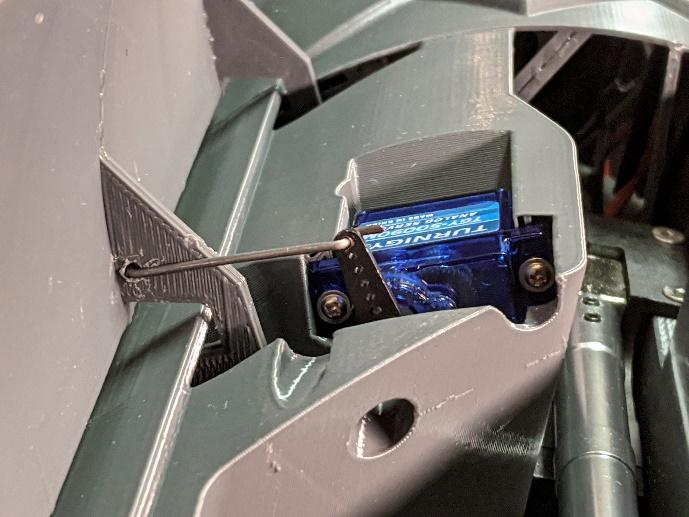
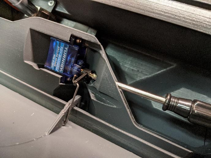
Push the servo arms onto the main gear door servos. The "center" position of the servo should be roughly the middle of the gear door's travel. Secure with a screw.
-
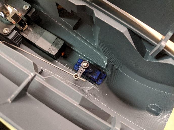
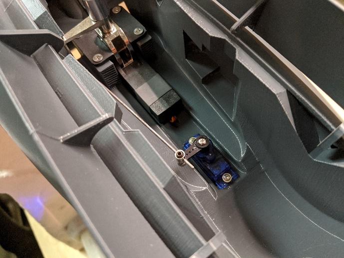
Screw the nose wheel steering servo in place as shown. Ensure that the arm and wheel are both centered, then secure the pushrod with an ez-link and set screw.
-
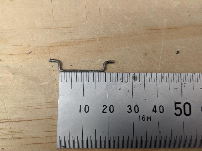
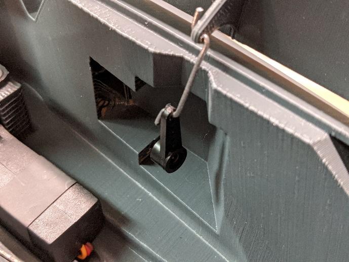
Make two nose gear door pushrods from thin wire as shown. Use a heated length of wire to clear the hole in the control horn of each gear door, then insert the pushrods.
-
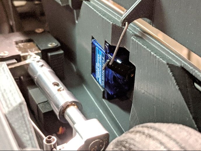
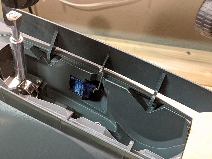
Install the nose gear door servos, center them, and connect the control arm. It may be easier to screw on the arm first. The "center" position of the servo should be roughly the middle of the gear door's travel.
-
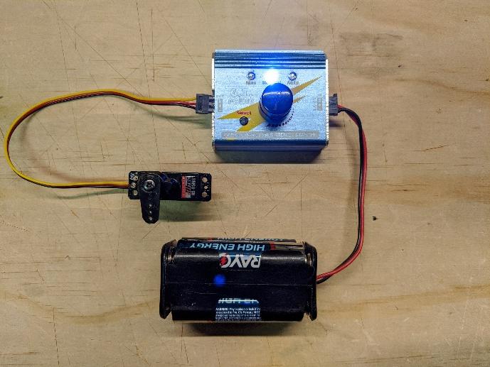
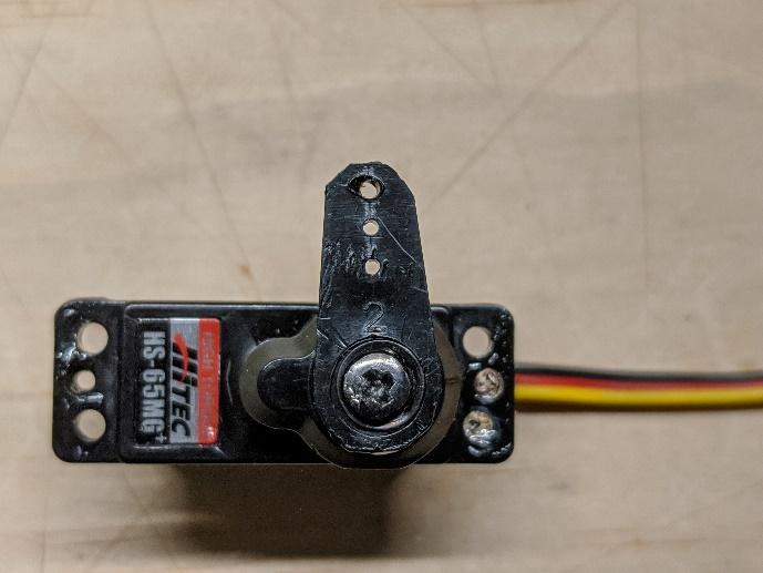
Center the ruddervator servos and install the control arms. Trim the control arms as shown.
-
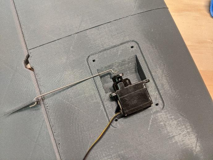
Dry fit the ruddervator servos into their pockets in the stabilizers. Bend pushrods to shape. Then, prepare the servos for installation by attaching double-sided servo tape.
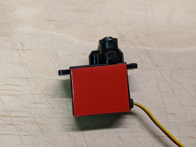
-
Connect the pushrods and install the ruddervator servos. Secure with the screws included with the servos. Afterwards, install the ruddervator servo covers with four small self-tapping screws.
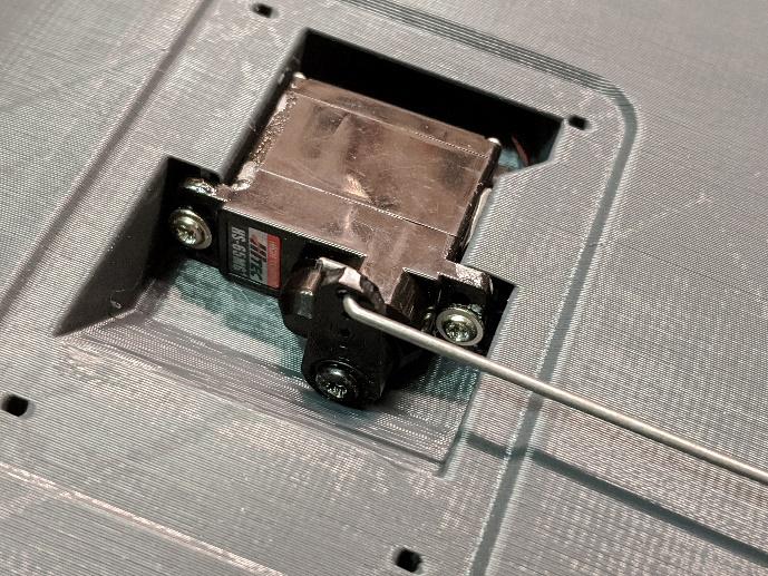
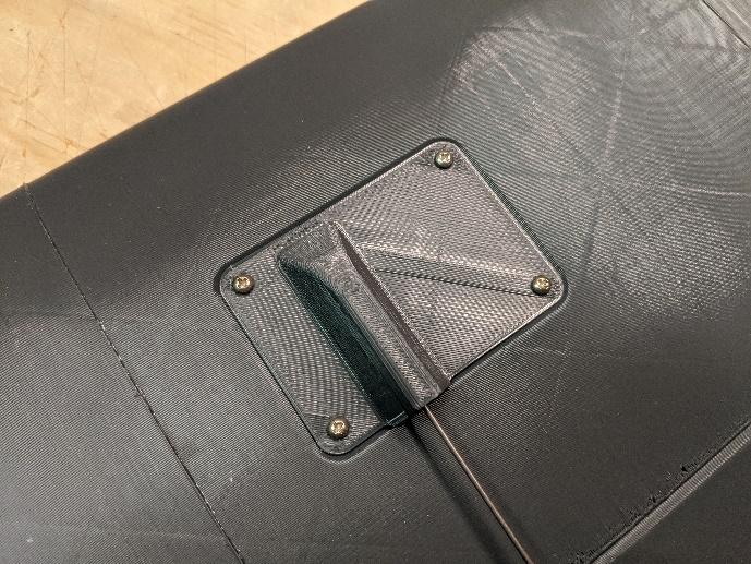
-
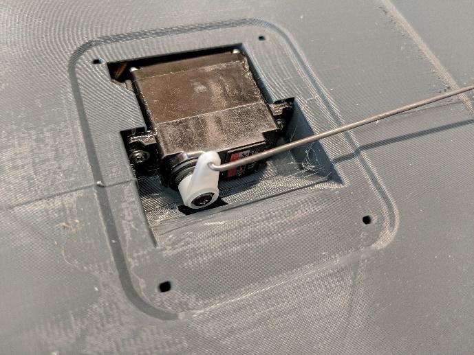
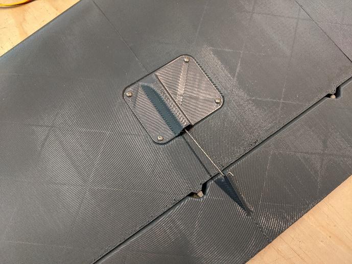
Center the flaperon servos and install their control arms.
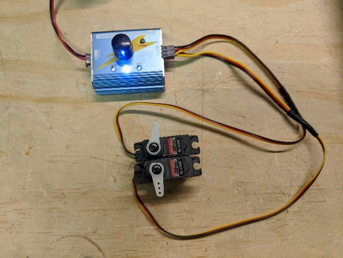
-
Install the flaperon servos and pushrods using the same method as the ruddervator servos. Install the flaperon servo covers with four small self-tapping screws each.
Power system installation
-
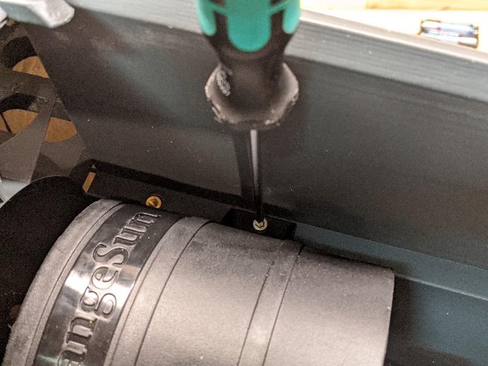
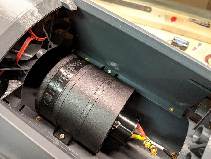
Install the EDF using two M3 x 6mm socket head cap screws and the middle set of threaded inserts.
-
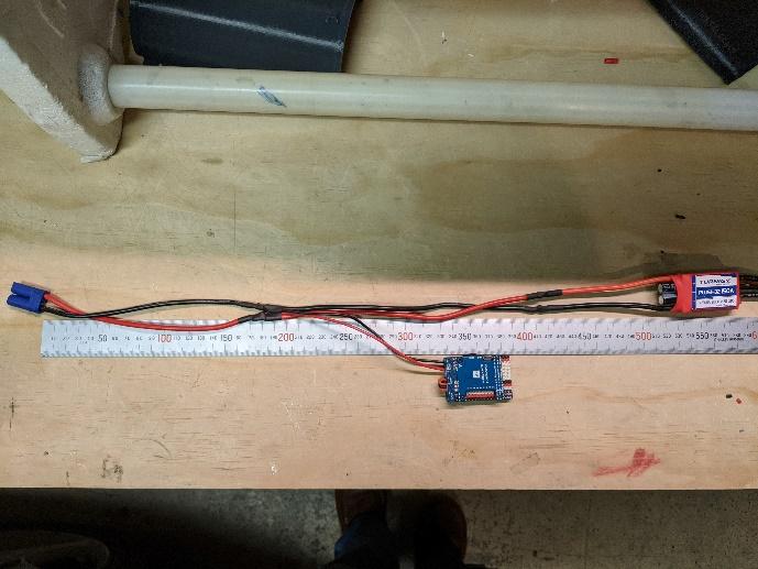
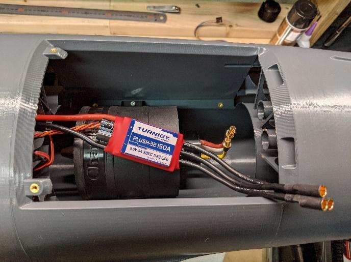
Solder power leads to your ESC for ~520mm of total length. Be sure to include power leads for your flight controller, BEC, or other accessories where needed. Slide them down the wiring tunnel in the fuselage.
-
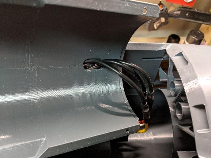
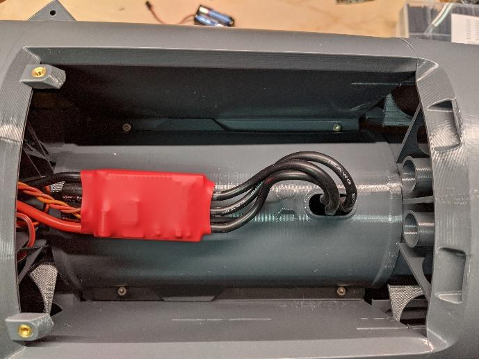
Thread the bullet connectors through the wiring cutout, then install the fan cover with four M3 x 6mm socket head cap screws.
-
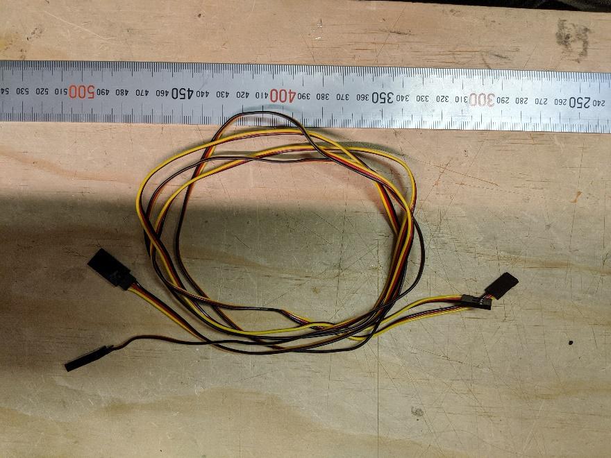
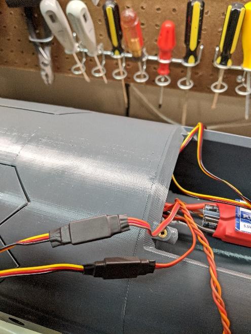
Connect servo extensions to the ESC (~250mm) and main retracts (~400mm). Also, run two ~900mm servo extensions through the tubes to the stabilizers for the ruddervator servos. Use heat shrink or locking clips to secure.
-
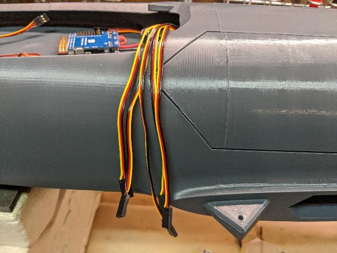
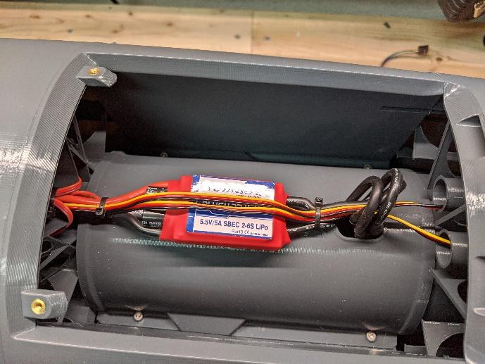
Run all the extensions through the wiring channel in the fuselage such that they exit inside the avionics bay with approximately the length shown. Secure the wiring in the EDF bay with cable ties.
-
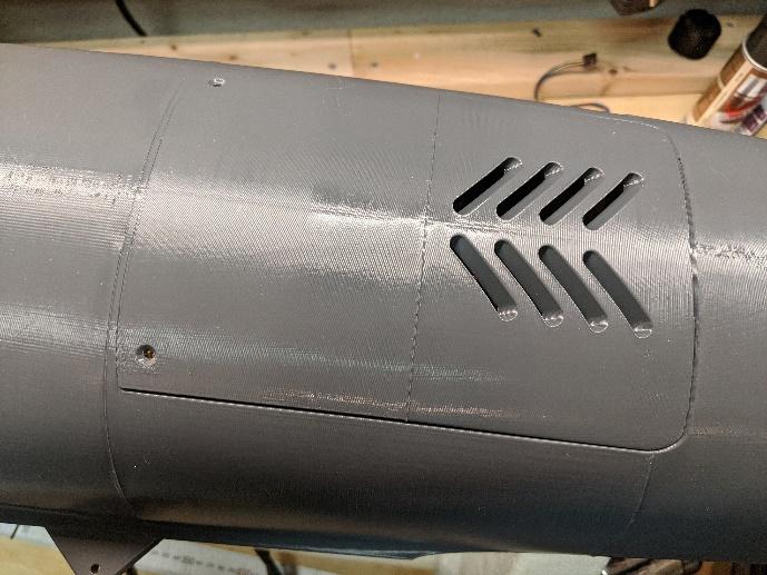
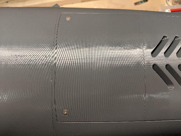
Attach the fan hatch with two M3 x 6mm flat-head screws.
Avionics installation
-
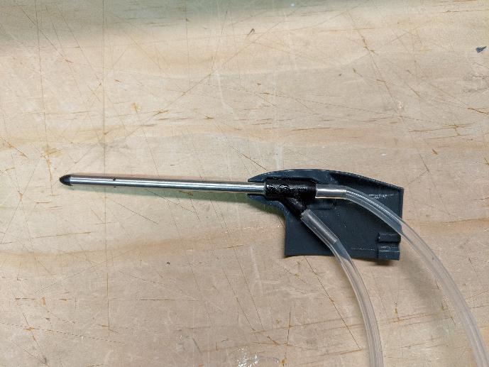
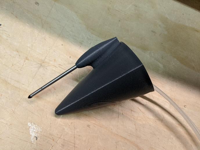
If using an airspeed sensor, trim the tubes of the pitot probe and mount it inside the pitot probe holder with CA. If not using an airspeed sensor, skip to step 3.
-
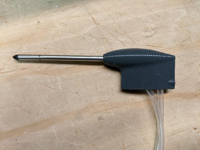
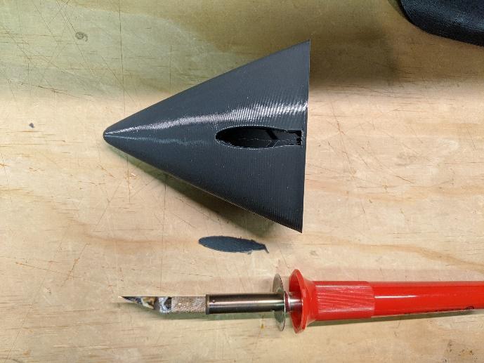
Use a hot knife to remove the floor of the pitot probe pocket in Fuselage 1. Then, slide the pitot holder in.
-
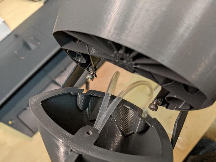
Screw two M3 x 6mm socket head cap screws into the holes shown in Fuselage 2, just enough to tightly engage the slots on Fuselage 1. If using an airspeed sensor, tuck the tubes into the cavity shown.
-
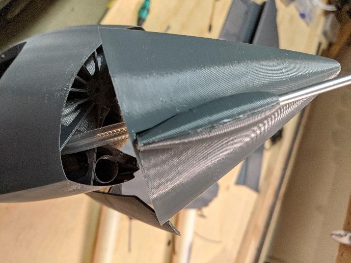
Slide Fuselage 1 onto the two screws in Fuselage 2. From inside, fasten it in place using another M3 x 6mm socket head cap screw.
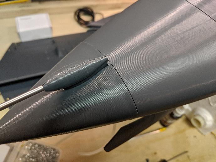
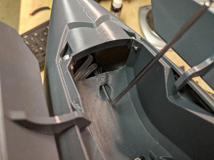
-
If using an airspeed sensor, mount as shown.
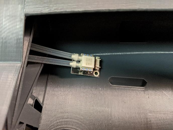
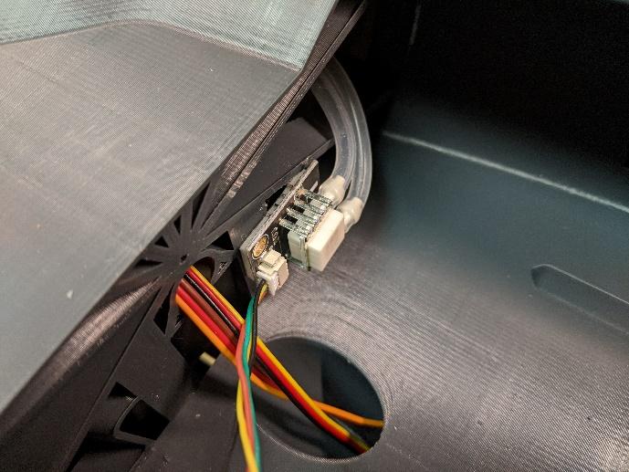
-
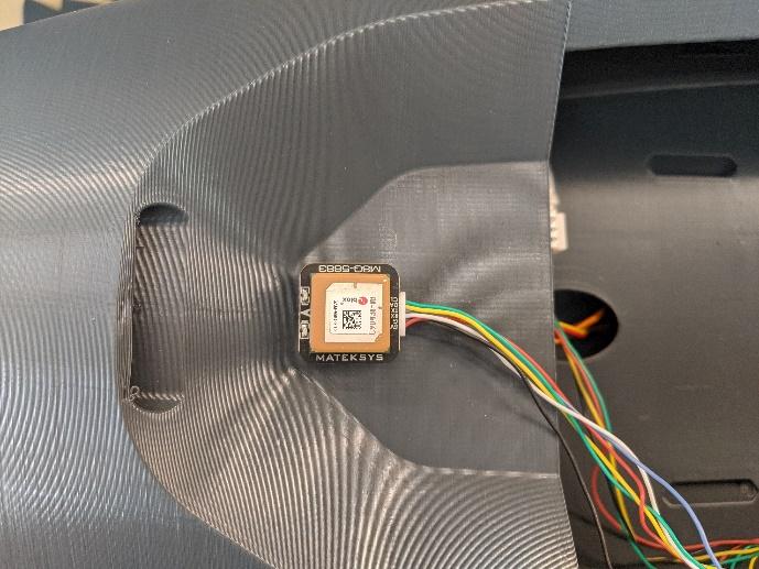
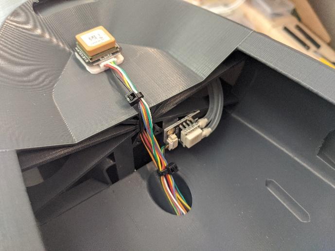
If using a GPS module, mount in the location shown with double-sided tape. Secure excess wiring with cable ties.
-
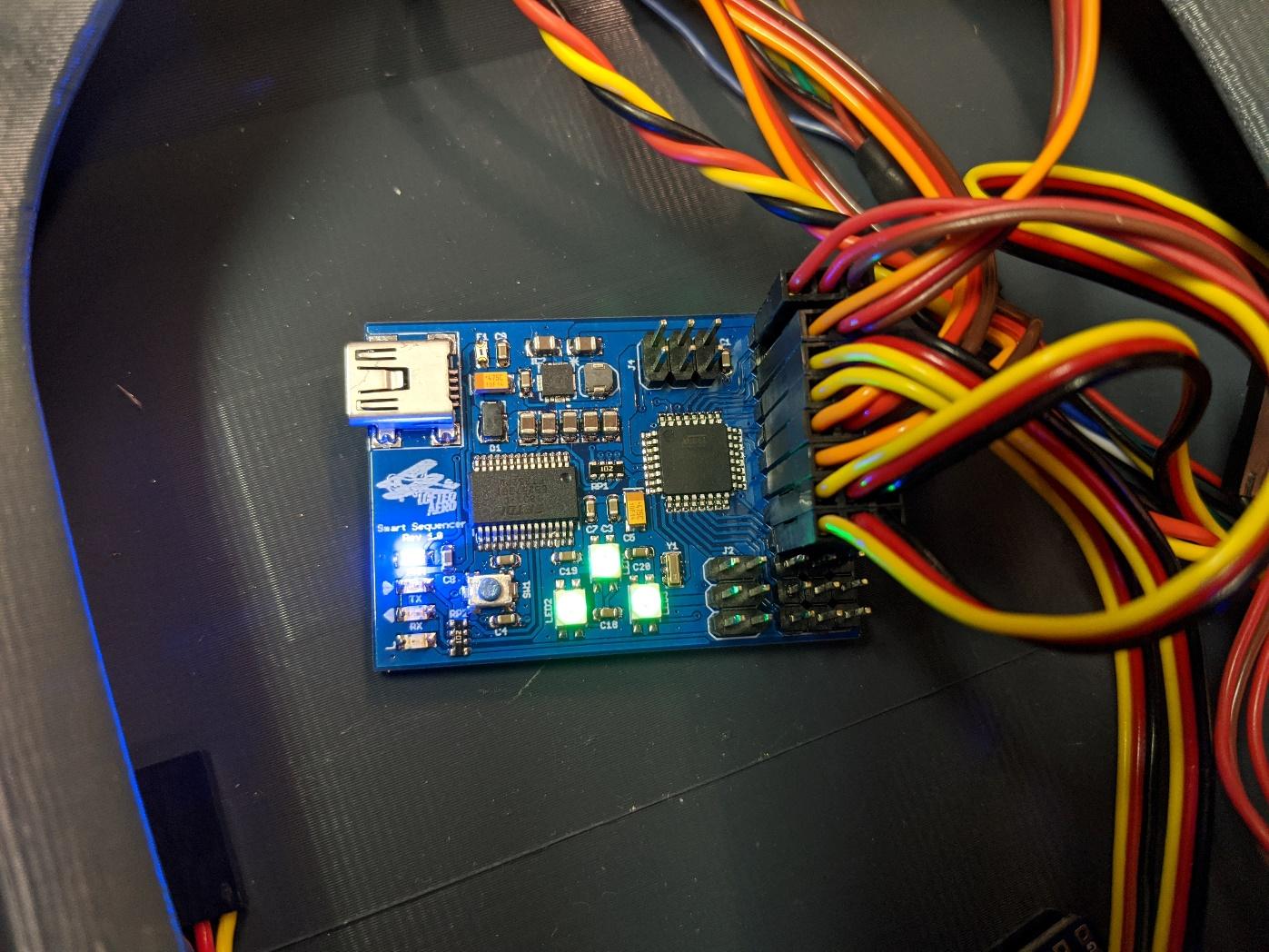
Connect the servo extensions from the retracts and gear door servos to the landing gear sequencer. Follow the sequencer's instructions for setup.
Electronics setup & finishing
-
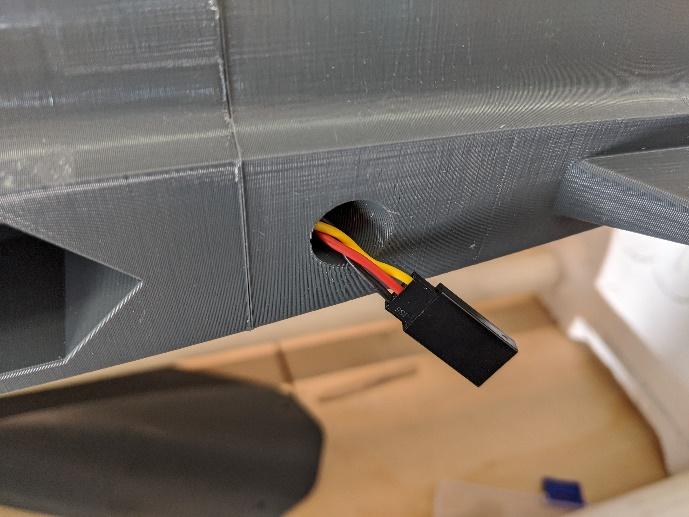
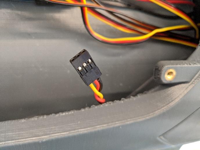
Run some ~500mm servo extensions for the flaperon servos through the tubes in the fuselage. They should protrude from the end of the tubes as shown.
-
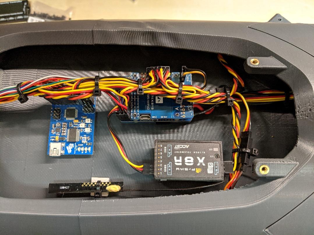
If using a flight controller, arrange it along with your R/C receiver inside the avionics bay. Connect the sensors, inputs, and outputs as per the flight controller documentation. If not using a flight controller, wire the servos and sequencer directly to your receiver.
Note
This model has many servos and retracts so be sure to use a BEC capable of powering them all. If you can, using one BEC to power the receiver and servos and another to power the landing gear is preferred. In the prototype, the Matek flight controller's powerful built-in BEC was used to power the servos while the ESC's built-in BEC was wired to power the gear sequencer, retracts, and doors.
-
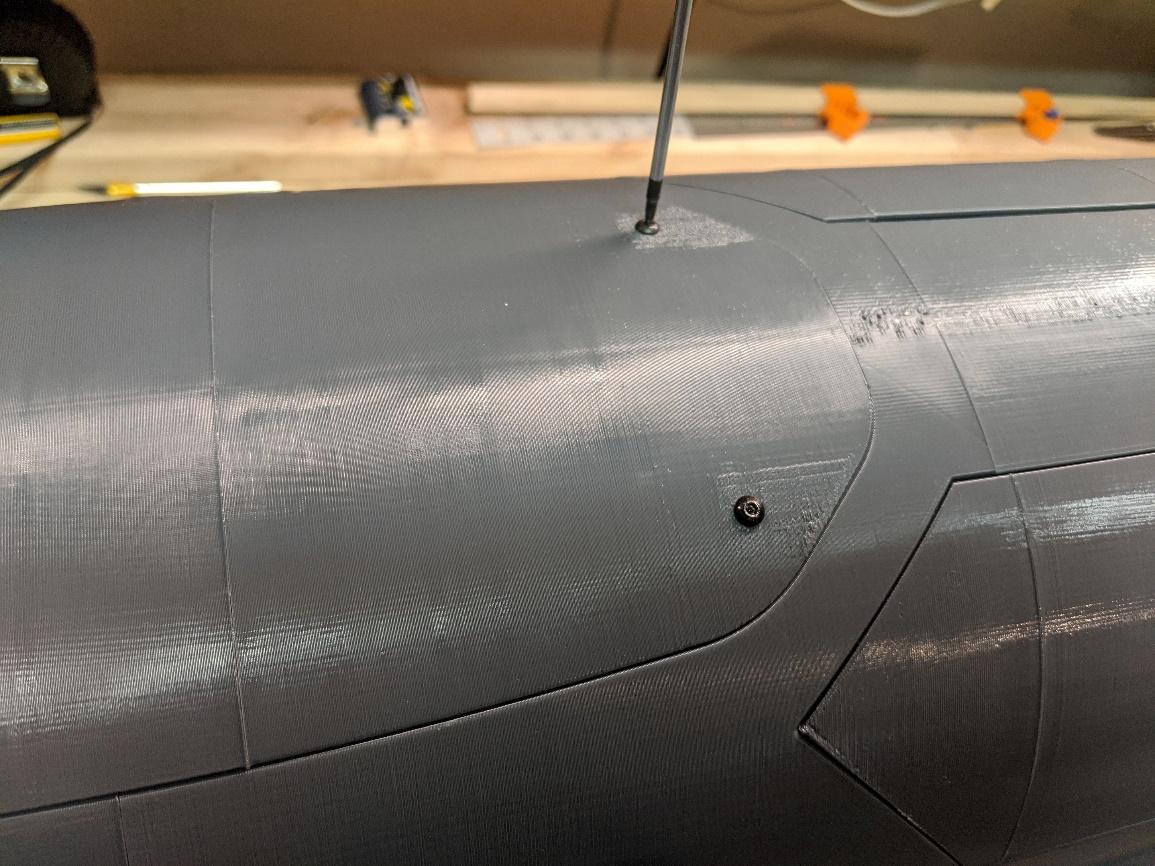
Install the avionics hatch and secure with two M3x6mm flat-head screws.
-
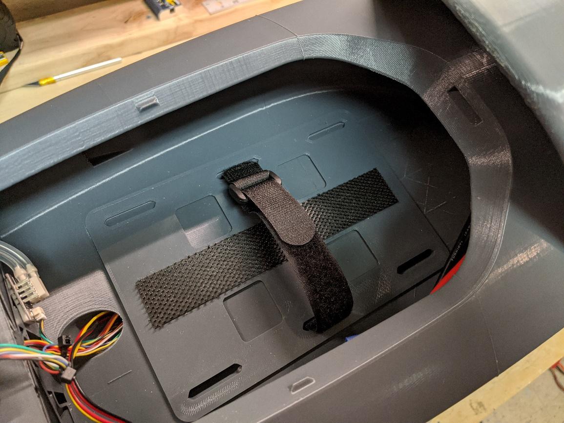
Glue in the battery tray to reinforce the floor of the battery bay. Be sure to align the slots with those in the floor. Install Velcro and straps to secure your battery.
-
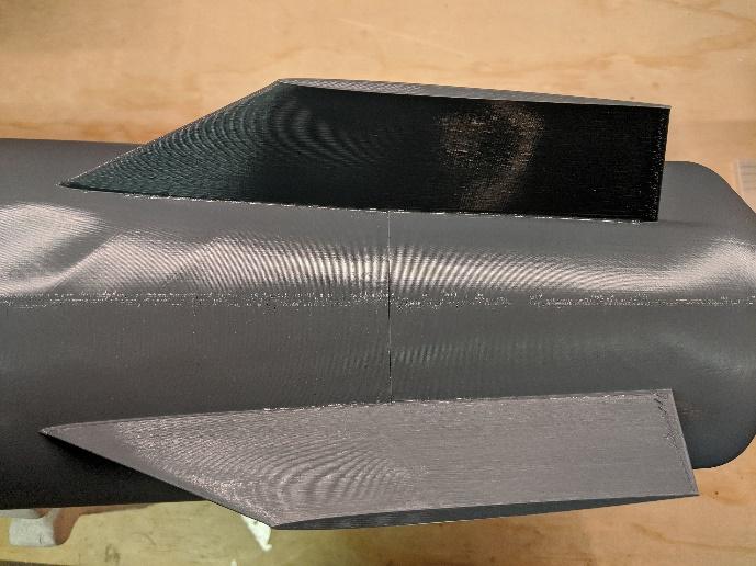
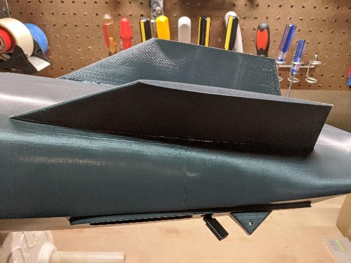
Install the ventral fins using CA.
-
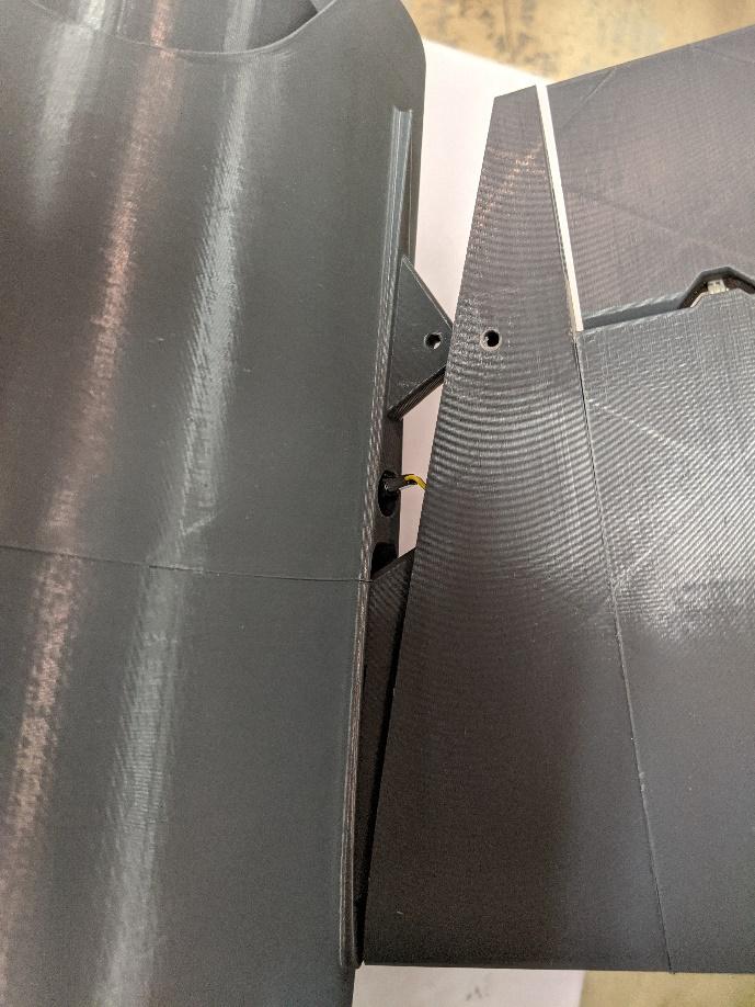
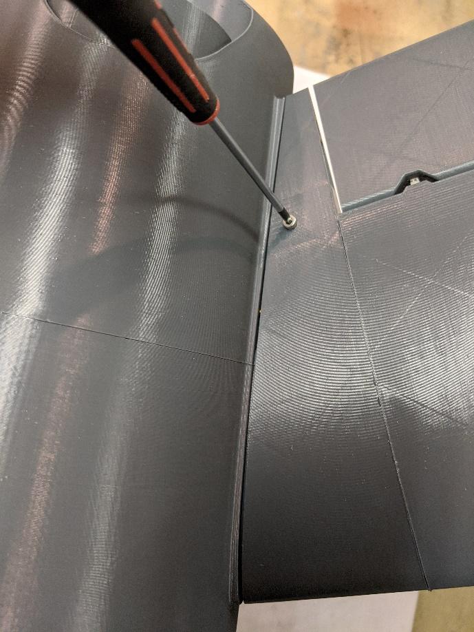
Slide the stabilizers into their slots in the fuselage, while connecting the servo leads and tucking them into their tubes. Secure with an M3x16mm cap screw.
-
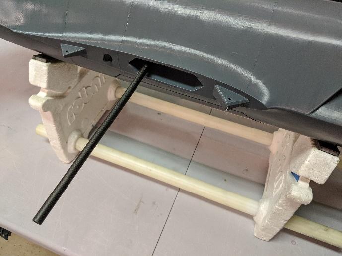
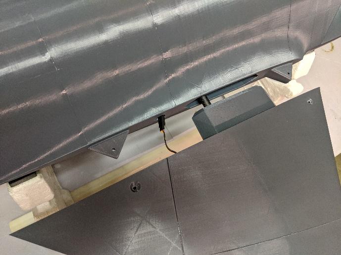
Prepare the 10mm diameter, 695mm long carbon fiber wing tube and insert it into the fuselage. Slide the wing panels onto the spar tube.
-
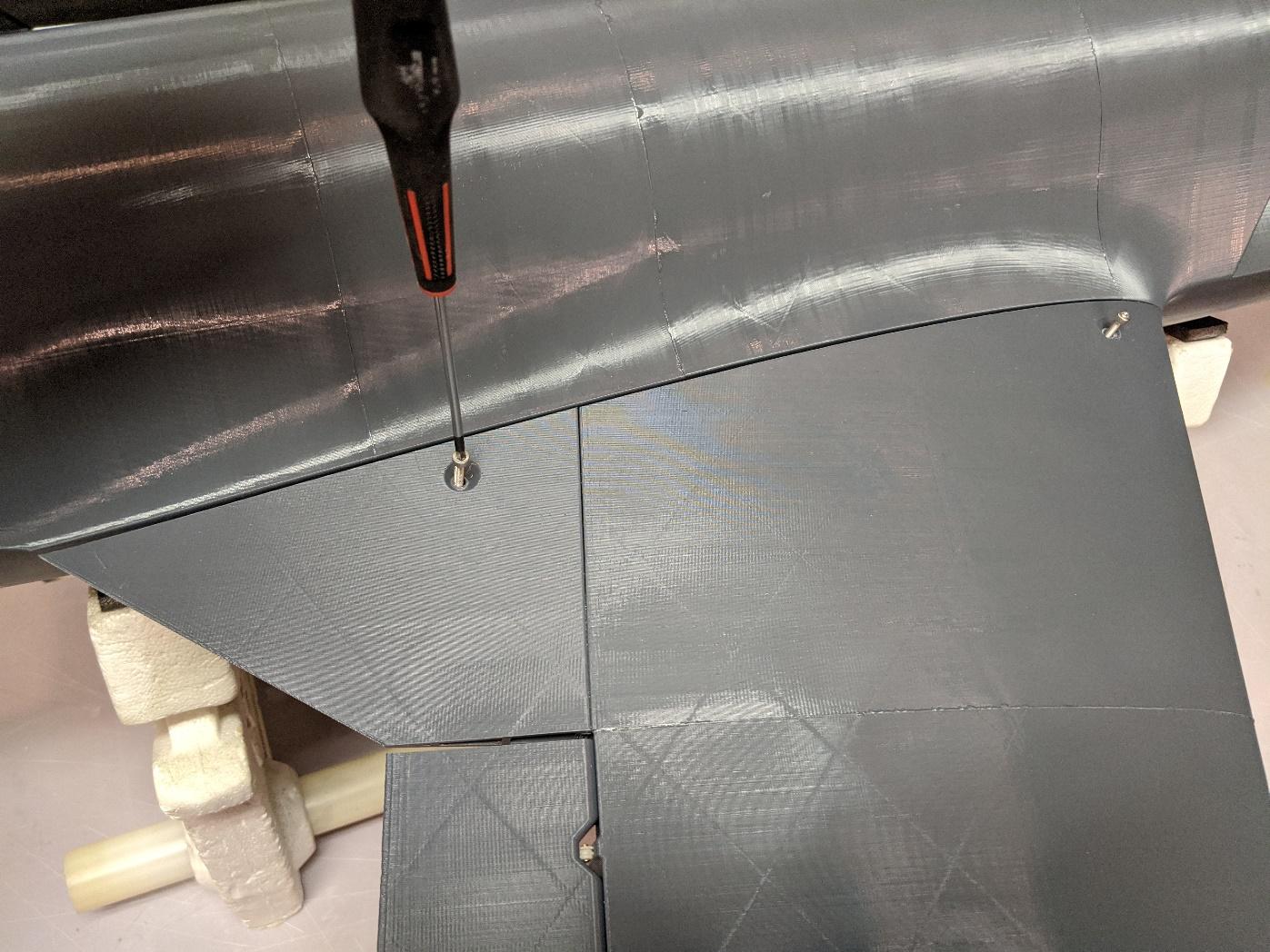
Fasten the wing panels using an M3x20mm cap screw at the rear and an M3x30mm cap screw at the front.
Adjust control deflections using the suggested throws below. Dual rates are optional depending on your preferences. Though regardless, consider using 25% - 50% expo for a smooth the control response.
Suggested control throws
| Control | Travel |
|---|---|
| Aileron | 10 mm up / 10 mm down |
| Elevator | 15 mm up / 15 mm down |
| Rudders | 15 mm left / 15 mm right |
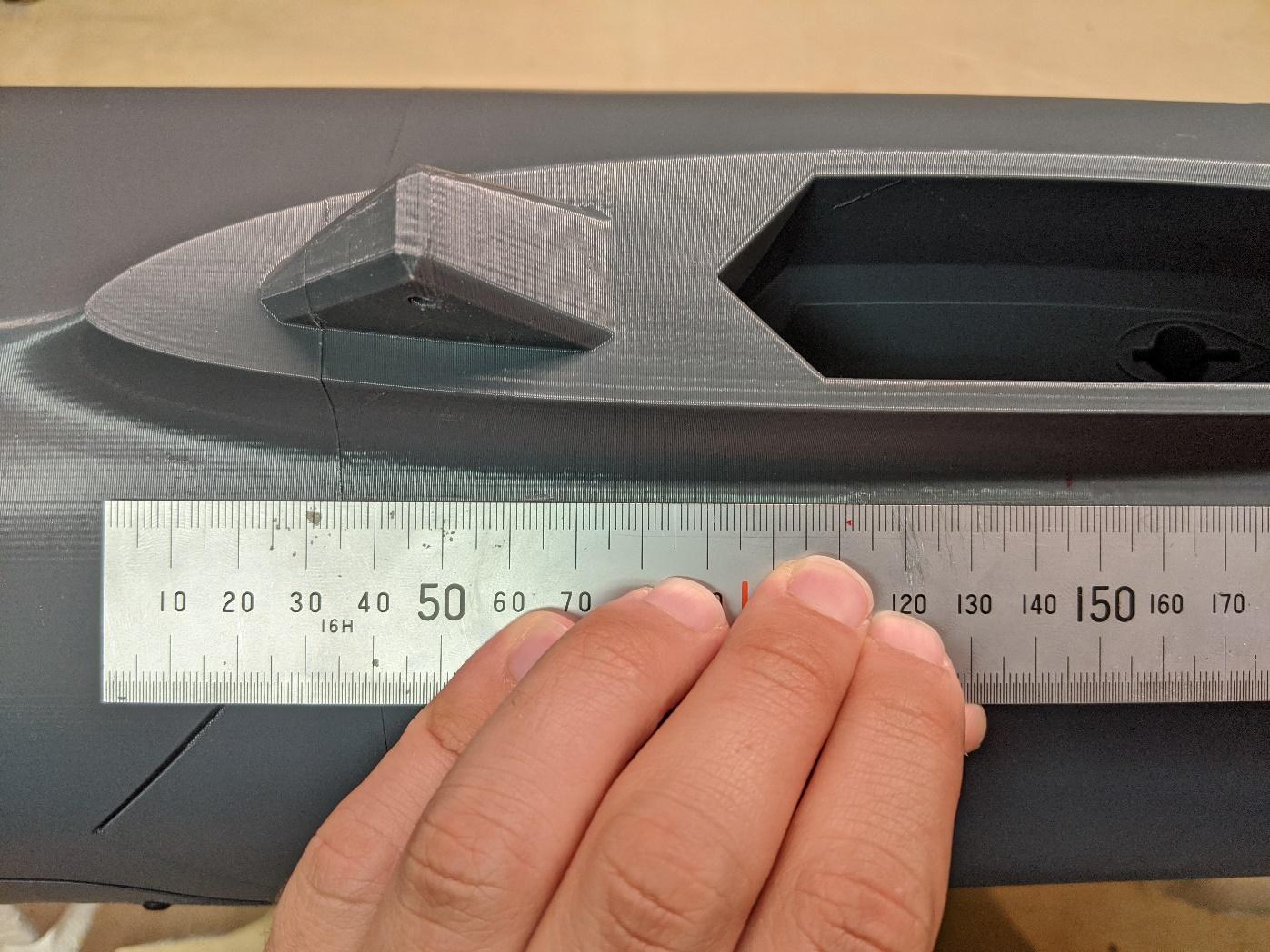
The recommended CG is located 145mm behind the wing leading edge at the root. Ensure that the model balances at this location with the battery, electronics, and all hatches installed. The landing gear should be extended during balancing.
Apply graphics if desired. You're ready to fly!
Contact us
Have a question, issue, or just a cool idea for the next aircraft we should model? Drop us an email at: info@loftedaero.com