Three-Bearing Swivel Module (3BSM) - 90mm — Reference Guide
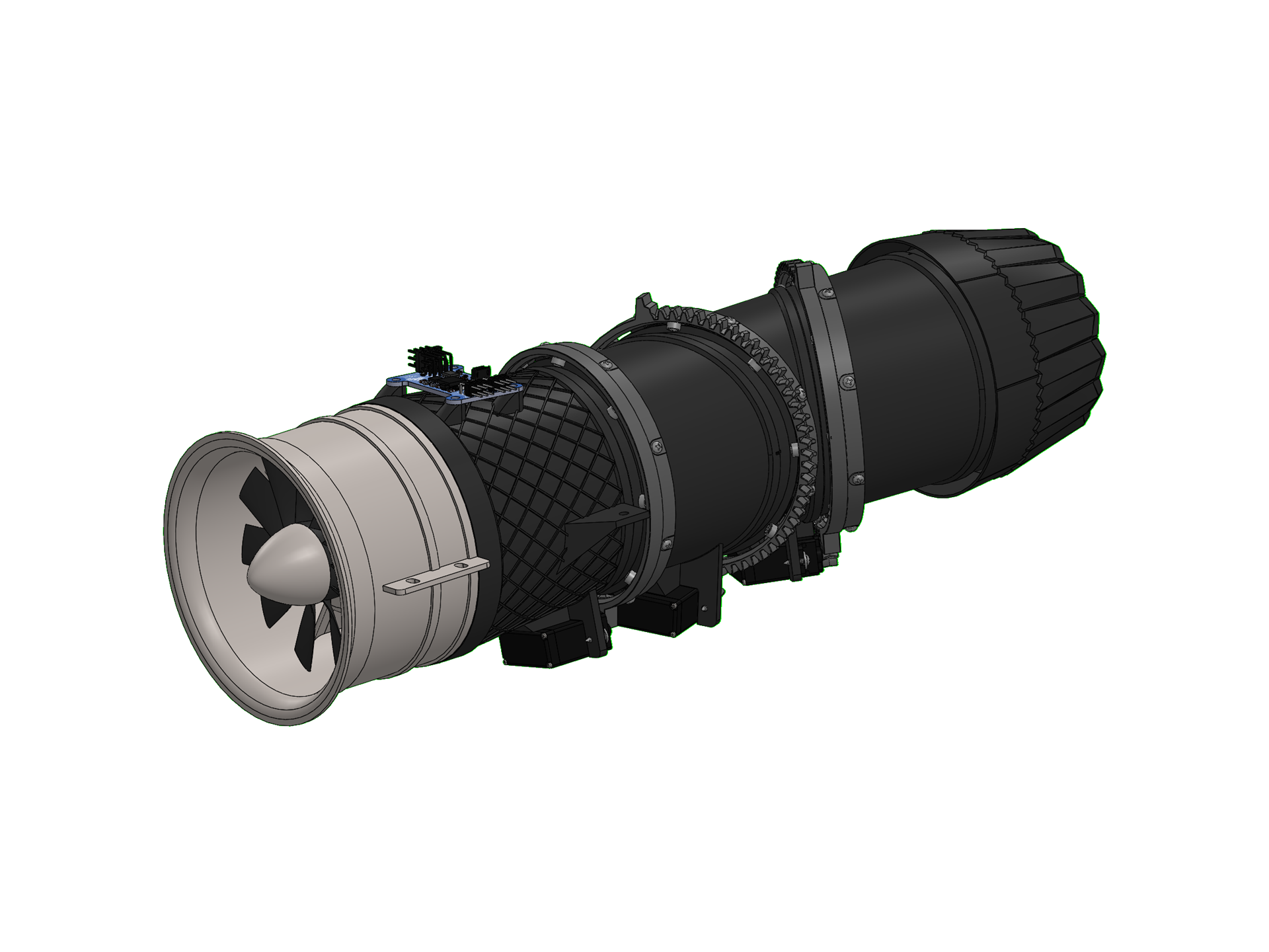
At a glance
- EDF size: 90 mm
- Length: 292 mm (not including EDF)
- Print weight: ~170 g
- Transition angle range: 0 – 105°
Overview
Thank you for purchasing a model by Lofted Aero! 3D printed aircraft are an exciting new segment of the hobby, and we've got no shortage of ideas for new designs. Your support helps us make those reality.
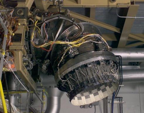
Vertical takeoff or landing - VTOL - is among the toughest challenges in aeromodelling. This is especially true when you throw ducted fans into the mix. Fortunately, 3D printing is here to help. This three-bearing swivel module (3BSM) model mirrors the design used on the F-35B jet. When coupled with the right electronics and software, you can create ducted fan VTOL models of your own!
Skill meter
Build: While this design is a straightforward configuration to print and assemble, it has numerous intricate assemblies and moving parts. It's best for builders who have prior experience building 3D printed models.
Specifications
| Spec | Value |
|---|---|
| EDF Size | 90mm |
| Length | 292mm (not including EDF) |
| Outlet Diameter | 72mm |
| Print Weight | ~170g |
| Transition Angle Range | 0 – 105 Degrees |
| Yaw Angle Range | +/- 15 degrees |
| Ring Gear Ratio | 8.25:1 |
Recommended equipment
The following hardware & electronics are required to complete the 3BSM. In addition, you'll need some CA glue and activator, your R/C transmitter and receiver, and a model to install it in!
Power system & avionics
| Item | Details |
|---|---|
| Motor & EDF | FMS 90mm Special Metal EDF for 8S |
| Servos (3x) | Hitec MD89MW-CAN |
| Servo Programmer | Hitec DPC-CAN |
| Control Board | Lofted Aero 3BSM Controller |
An electronics pack containing the control board, servos, and programmer at a substantial bundle discount is available from Lofted Aero HERE.
Filament
Good filament matters more here than on most prints. The materials below have been tested with our filament and process settings and produce good results.
| Use | Filament | Amount |
|---|---|---|
| PLAStructure, accessories, and thin-wall airframes. | 3DLabPrint PolyAir or eSun PLA+ or Bambu PLA Tough+ | ~161 g |
Hardware
| Item | Qty | Part |
|---|---|---|
| Bearings | 48 required | 50pcs MR52ZZ Bearings |
| Bearing Mount Screws | 48 required | M2 x 5 Flat Head Screw, 25-pack (x2) |
| General Assembly Screws | 27 required | #2 x 3/16" Tapping Screw, 50-pack |
| Servo Mount Screws | 6 required | #2 x 5/16" Tapping Screw, 100-pack |
| Servo Mount Washers | 6 required | #2 Flat Washer, 100-pack |
| Control Board Mount Screws | 4 required | M3 x 6mm Socket Cap Screw, 100-pack |
A convenient hardware pack containing all inserts and fasteners is available from Lofted Aero HERE.
Printing thin-wall models
Desktop 3D printers are perfectly capable of producing great-flying R/C models durable enough to withstand hangar rash and general use. However, aircraft designs contain a unique mix of thin surfaces and intricate solid supports that require some practice to print perfectly. Keep the following tips in mind when printing your model.
Slicing the project files
The model download includes .3MF project files for both Bambu Studio and OrcaSlicer – modern, free, and open source slicers with wide support for popular printers and the ability to utilize multiple plates and varying settings within a single project. These project files include print settings tailored to the model as well as filament settings with adjusted temperature and retractions. The provided settings have been tested to suit a wide range of printers – in most cases, no changes should be necessary aside from choosing your printer.
Open the folder for the slicer you're running. The two sets are equivalent and the workflow is the same in both, but each is written in its own slicer's settings dialect, so they aren't interchangeable.
- Choose your printer from the drop-down menu.
- The project already has the right filament and process settings selected, so it will slice correctly as-is.
- Import our presets once from the Print Settings page to keep them in your slicer for future projects.
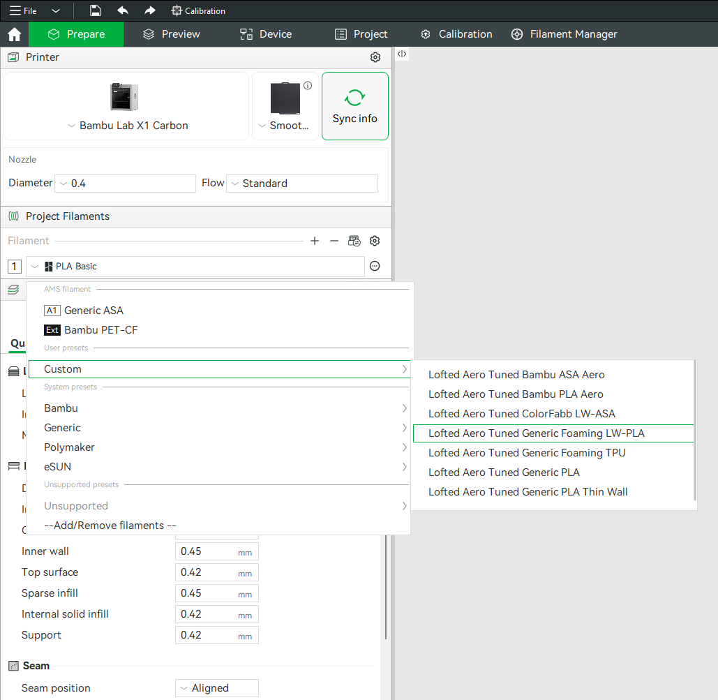
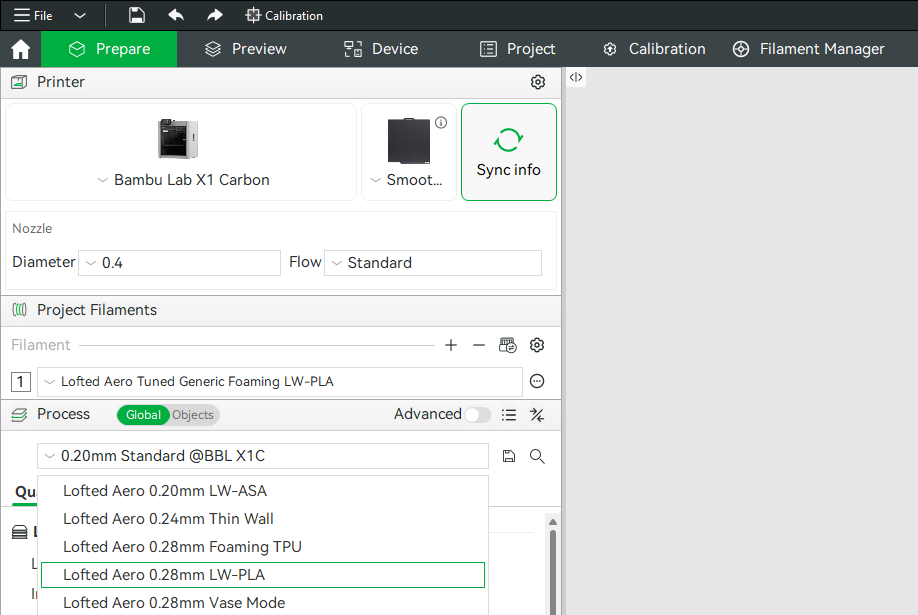
Generic example screenshots
These happen to show the LW-PLA profiles being picked. The profiles this model uses are listed just below.
Profiles used by this model
| Project file | Process profile | Filament profile |
|---|---|---|
| PLA Parts | Your slicer's own 0.20mm Standard |
Lofted Aero Tuned Generic PLABambu Studio OrcaSlicer |
Hardware parts like latches, trays, mounts and gear ride your slicer's own stock profile, which is already matched to your printer.
Modifiers and per-object settings
Both slicers allow per-object modifications to slicing settings, and this method is used heavily in the provided .3MF files. Where a part needs extra perimeters, different infill, or a relocated seam, that's applied as a per-object modifier on top of the profile rather than as a separate profile. When making settings changes, be mindful of these per-object settings as well as any other modifiers applied to each part. Switch the Process panel from Global to Objects to see every part in the project, the settings overridden on it, and any modifier volumes attached to it.
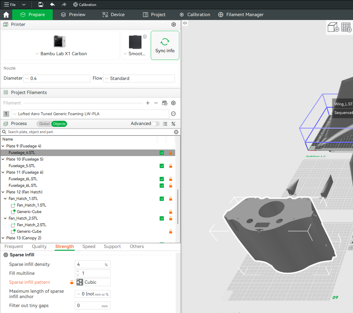
(example screenshot shown – may not represent this model)
Mirrored parts
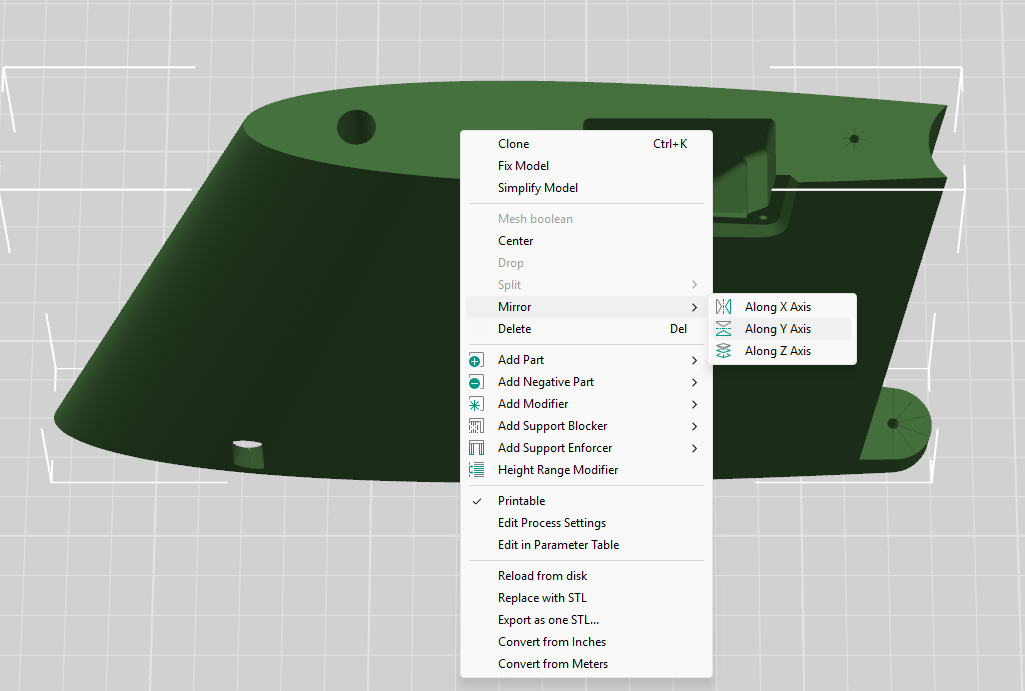
You'll notice that the included STL files often contain parts for only one side of symmetrical components like wings, tail surfaces, and landing gear. Don't worry – you can simply mirror these parts in your slicer to produce the other side. When using the included .3MF project files, this mirroring has already been done.
Other printing options
If you'd rather configure and slice the STL files yourself with the software and method of your choice, refer to the print table below for the profile and modifiers applied to each part.
A few things to keep in mind:
- Retraction should be just enough to prevent stringing between features
- Extra length on restart should be just enough to prevent sparse extrusion at layer start
- Extrusion ratio should be adjusted until print weight equals the suggested part weight
Print table
Reference print profiles, per-part modifiers, and weights for each part.
| Part | Weight | Print Profile | Modifiers |
|---|---|---|---|
| 3BSM Parts | |||
| Sections 1-4 | 86g total | Your slicer's own 0.20mm Standard0.20mm Height 0.42mm Extrusion Width 2 Perimeters 5 Top / 3 Bottom Layers 15% Infill (Grid in Bambu Studio, Cross Hatch in OrcaSlicer) Aligned Seam Classic Wall Generator 210°C Nozzle / 60°C BedModifiers on every part in this group:Arachne Wall Generator |
|
| Nozzle | 26g |
| |
| Ring Inserts | 12g total |
| |
| Ring Gears | 27g total |
| |
| Pinion Gears | 2g total |
| |
| Servo Mounts | 8g total |
| |
| Total 3BSM Parts | 161g | ||
Pinion gear servo spline
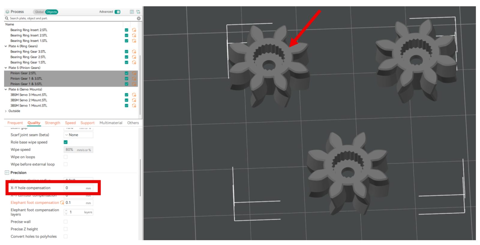
The pinion gears must precisely fit the servo output splines and are printed at a lower layer height and extrusion width to enable this. They are designed to fit tightly, though results may vary between printers. If your pinion gears fit too loosely or too tightly, adjust the "X-Y hole compensation" value in increments of +/- 0.05 until you achieve a proper fit.
Assembly
A video guide series outlines assembly of the 3BSM. Watch each video below.
Mechanical assembly
Electronics installation
Software setup
Contact us
Have a question, issue, or just a cool idea for the next aircraft we should model? Drop us an email at: info@loftedaero.com