T-38C for 50mm EDF — Build Guide
At a glance
- Difficulty: Beginner to build, intermediate to fly
- Wingspan: 575 mm (22.6")
- Length: 1000 mm (39.4")
- Flying weight: 650–750 g (1.4–1.7 lb)
Overview
Thank you for purchasing a model by Lofted Aero! 3D printed aircraft are an exciting new segment of the hobby, and we've got no shortage of ideas for new designs. Your support helps us make those reality.
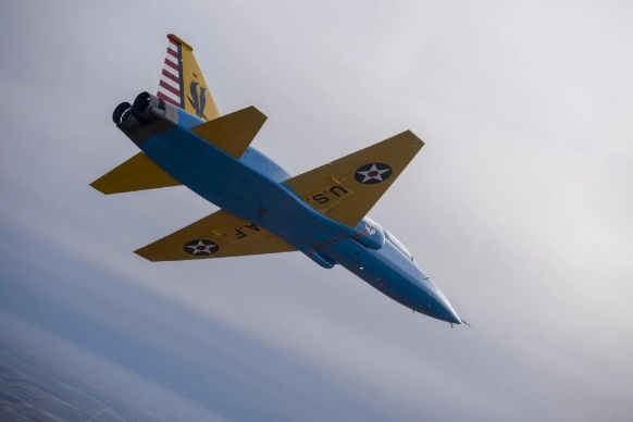
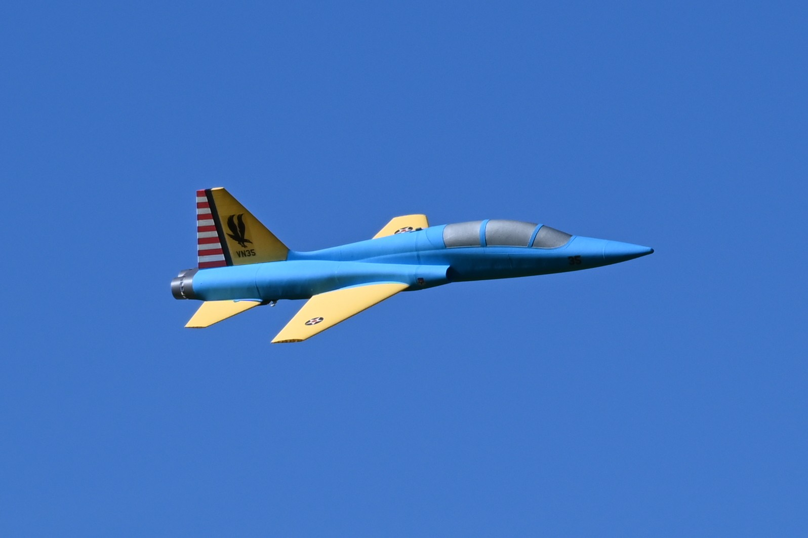
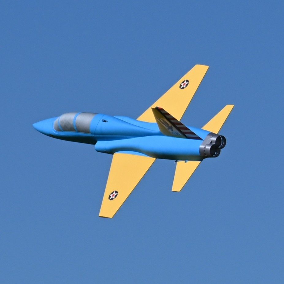
The T-38C is an exciting EDF jet designed to be quick and economical to build without sacrificing design details or scale looks. It delivers impressive performance and handling, with a wide speed range and crisp maneuverability.
Skill meter
Build: With a simple design and low parts count, this build is just about as easy as it gets! It is well suited to be an R/C pilot's first transition into 3D printed models.
Flight: This model has good handling characteristics despite its small wings. But it's still a fast, nimble jet that is best flown by pilots of intermediate skill or above.
Specifications
| Spec | Value |
|---|---|
| Wingspan | 575mm (22.6") |
| Length | 1000mm (39.4") |
| Wing Area | 9.04dm2 (0.973ft2) |
| Print Weight | ~300g |
| Flying Weight | 650-750g |
| Wing Loading | 72-83g/dm2 (24-27oz/ft2) |
| Airfoil | RG-15 modified |
Recommended equipment
The following hardware & electronics are required to complete this model. In addition, you'll need some CA glue and activator, your R/C transmitter and receiver, and a LiPo battery charger.
Power system & avionics
| Item | Details |
|---|---|
| EDF | XFly 50mm EDF for 4S Or FMS 50mm EDF for 4S |
| ESC | 40A ESC or Similar |
| Battery | 4S 1300 – 1800mAh LiPo (a 4S 1550mAh pack is a good fit) |
| Servos | 9g Metal Gear (only 2x required) Or FMS 9g Metal Gear with 300mm Wire |
| Servo Extensions | 300mm/12" |
Filament
Good filament matters more here than on most prints. The materials below have been tested with our filament and process settings and produce good results. Alternate options are listed as well, though weight and durability may vary.
| Use | Filament | Amount |
|---|---|---|
| LW-PLAAirframe skins — wings, tail and fuselage. | 3DLabPrint PolyLight or ColorFabb LW-PLA or Bambu PLA Aero | ~252 g |
| PLAStructure, accessories, and thin-wall airframes. | 3DLabPrint PolyAir or eSun PLA+ or Bambu PLA Tough+ | ~49 g |
| Alternate material options | ||
| LW-ASA replaces LW-PLAHeat and UV resistant. Needs a heated enclosure and the 0.20mm LW-ASA profiles — see Profiles used by this model. | ColorFabb LW-ASA or Bambu ASA Aero | — |
| PETG replaces PLAHigher heat tolerance. Same process profile — load your slicer's own PETG filament preset. | Bambu PETG Basic or Hatchbox PETG | — |
Hardware & structure
| Item | Details |
|---|---|
| Wing Spar Tube | Carbon Fiber 6mm x 4mm x 400mm Tube (only 1x required) |
| Stabilator Hinge Tube | Carbon Fiber 4mm x 3mm x 400mm Tube (only 1x required) |
| Pushrods | 1.2mm Pushrods with Linkage Stoppers (only 2x required) |
| Fan and Hatch Mounting Screws | #2 x 3/8" Tapping Screws (or equivalent, only 4x required) |
| Canopy Latch | Pen spring (available here) |
Printing thin-wall models
Desktop 3D printers are perfectly capable of producing great-flying R/C models durable enough to withstand hangar rash and general use. However, aircraft designs contain a unique mix of thin surfaces and intricate solid supports that require some practice to print perfectly. Keep the following tips in mind when printing your model.
Slicing the project files
The model download includes .3MF project files for both Bambu Studio and OrcaSlicer – modern, free, and open source slicers with wide support for popular printers and the ability to utilize multiple plates and varying settings within a single project. These project files include print settings tailored to the model as well as filament settings with adjusted temperature and retractions. The provided settings have been tested to suit a wide range of printers – in most cases, no changes should be necessary aside from choosing your printer.
Open the folder for the slicer you're running. The two sets are equivalent and the workflow is the same in both, but each is written in its own slicer's settings dialect, so they aren't interchangeable.
The process and filament presets these projects use are our own. You don't need them to print – the project files already carry the settings – but importing them once from the Print Settings page keeps them in your slicer for future projects, and that page explains what each one is for.
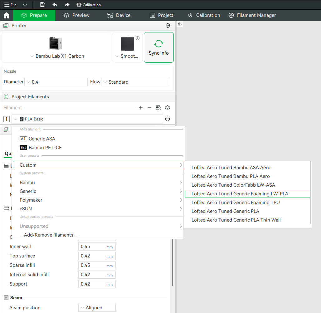
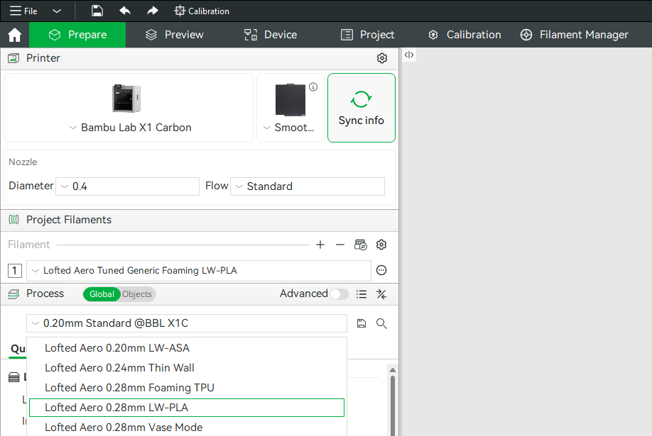
Generic example screenshots
These happen to show the LW-PLA profiles being picked. The profiles this model uses are listed just below.
Profiles used by this model
| Project file | Process profile | Filament profile |
|---|---|---|
| LW-PLA Parts | Lofted Aero 0.28mm LW-PLABambu Studio OrcaSlicer | Lofted Aero Tuned Generic Foaming LW-PLABambu Studio OrcaSlicer |
| PLA Parts | Your slicer's own 0.20mm Standard |
Lofted Aero Tuned Generic PLABambu Studio OrcaSlicer |
Hardware parts like latches, trays, mounts and gear ride your slicer's own stock profile, which is already matched to your printer.
Printing the airframe in LW-ASA instead? Substitute Lofted Aero 0.20mm LW-ASA for the LW-PLA process profile, with either the Bambu ASA Aero or ColorFabb LW-ASA filament profile from the Print Settings page. LW-ASA needs a heated enclosure. Everything else in the table is unchanged.
Modifiers and per-object settings
Both slicers allow per-object modifications to slicing settings, and this method is used heavily in the provided .3MF files. Where a part needs extra perimeters, different infill, or a relocated seam, that's applied as a per-object modifier on top of the profile rather than as a separate profile. When making settings changes, be mindful of these per-object settings as well as any other modifiers applied to each part. Switch the Process panel from Global to Objects to see every part in the project, the settings overridden on it, and any modifier volumes attached to it.
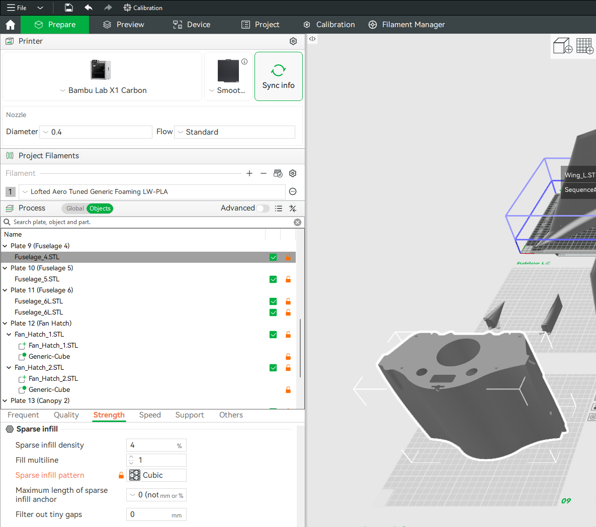
(example screenshot shown – may not represent this model)
Mirrored parts
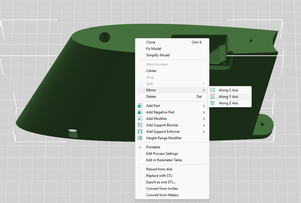
You'll notice that the included STL files often contain parts for only one side of symmetrical components like wings, tail surfaces, and landing gear. Don't worry – you can simply mirror these parts in your slicer to produce the other side. When using the included .3MF project files, this mirroring has already been done.
Other printing options
If you'd rather configure and slice the STL files yourself with the software and method of your choice, refer to the print table below for the profile and modifiers applied to each part.
A few things to keep in mind:
- Retraction should be just enough to prevent stringing between features
- Extra length on restart should be just enough to prevent sparse extrusion at layer start
- Extrusion ratio should be adjusted until print weight equals the suggested part weight
Print table
Reference print profiles, per-part modifiers, and weights for each part.
| Part | Weight | Print Profile | Modifiers |
|---|---|---|---|
| LW-PLA Parts | |||
| Wing L & R | 20g each | Lofted Aero 0.28mm LW-PLA0.28mm Height 0.42mm Extrusion Width 1 Perimeter 3 Top / 3 Bottom Layers 2D Lattice @ 4% Back Seam Classic Wall Generator 238°C Nozzle / 56°C Bed |
— |
| Stabilator L & R | 5.3g each | ||
| Vertical Tail | 12g | ||
| Fuselage 1 | 4g |
| |
| Fuselage 2 | 20g | ||
| Fuselage 3 | 31g | ||
| Fuselage 4 | 47g | ||
| Fuselage 5 | 35g | ||
| Fuselage 6 | 29g | ||
| Fan Hatch 1 | 2.2g |
| |
| Fan Hatch 2 | 2.3g |
| |
| Canopy 1 | 11g |
| |
| Canopy 2 | 7.5g |
| |
| Total LW-PLA Parts | 252g | ||
| PLA Parts | |||
| Stabilator Pivot Blocks | 2.1g each | Your slicer's own 0.20mm Standard0.20mm Height 0.42mm Extrusion Width 2 Perimeters 5 Top / 3 Bottom Layers 15% Infill (Grid in Bambu Studio, Cross Hatch in OrcaSlicer) Aligned Seam Classic Wall Generator 210°C Nozzle / 60°C Bed |
|
| Stabilator Stoppers | 0.4g each | — | |
| Servo Mounts | 1.5g each |
| |
| Battery Tray | 9g |
| |
| Cheater Inlet | 1.5g | — | |
| Hatch Latch | 4g |
| |
| Fan Hatch Tabs | 0.5g each | ||
| Fan Mount Tabs | 0.6g each | ||
| EDF Brace (optional) | 2.3g | — | |
| Belly Skid | 2.7g |
| |
| Rear Skids | 2g each | ||
| Nozzle | 15g |
| |
| Total PLA Parts | 49g | ||
Joining parts
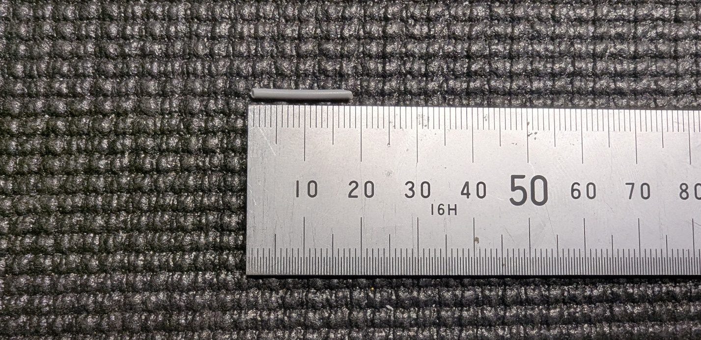
Unless otherwise specified, medium CA and activator are recommended for joining printed parts. In addition, many joints use ~18mm lengths of 1.75mm PLA filament for alignment. Preparing a handful of these ahead of time can help speed up the build.
Fuselage assembly
-
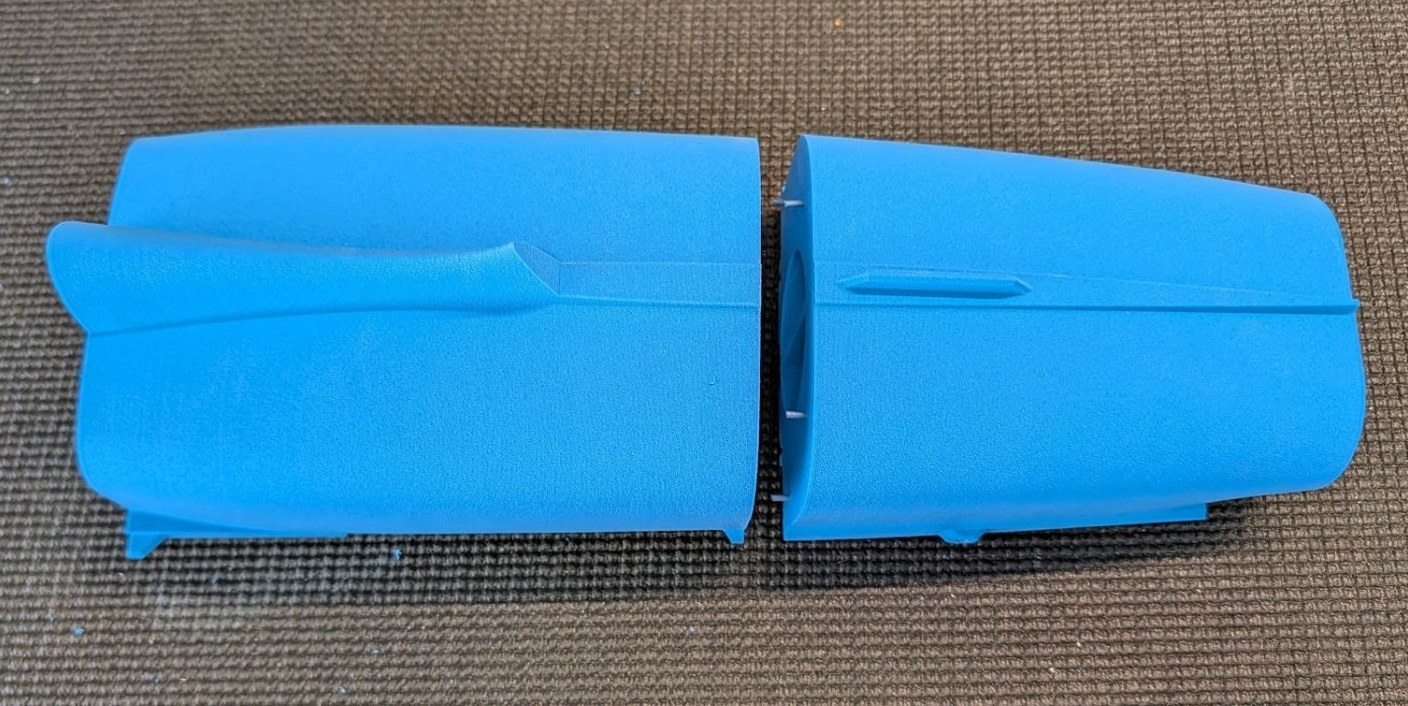
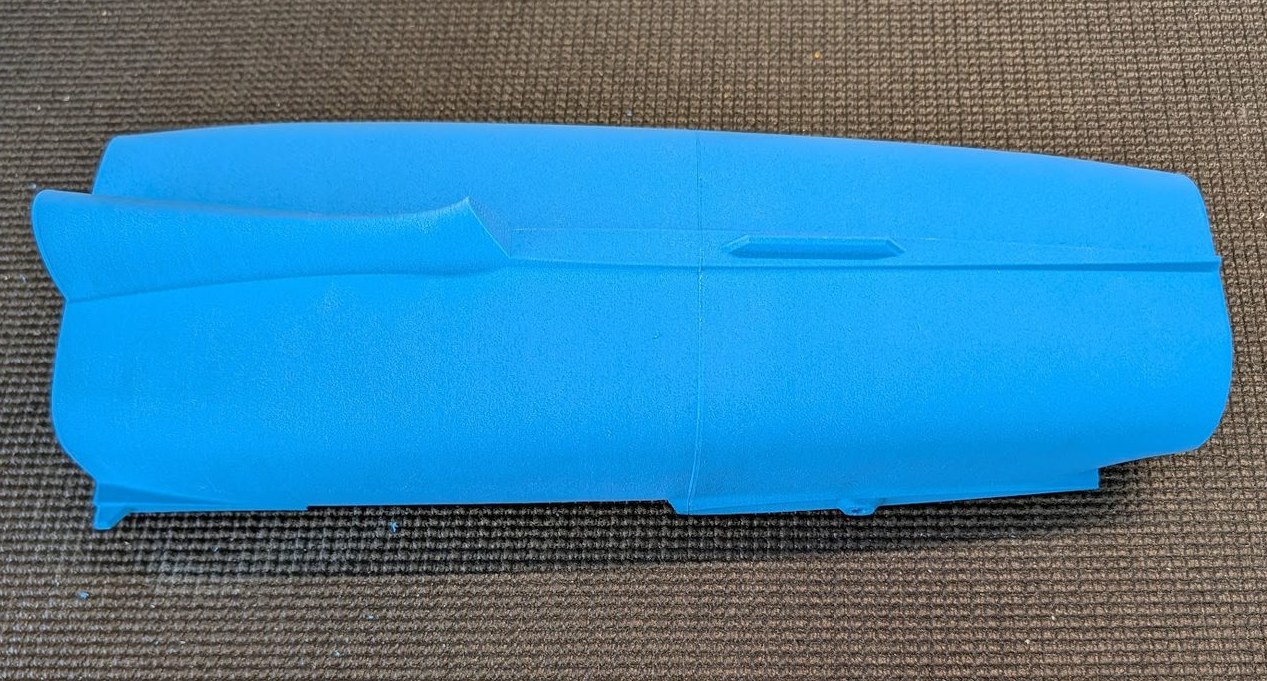
Using CA and filament alignment guides, glue fuselage sections 5 and 6 together.
-
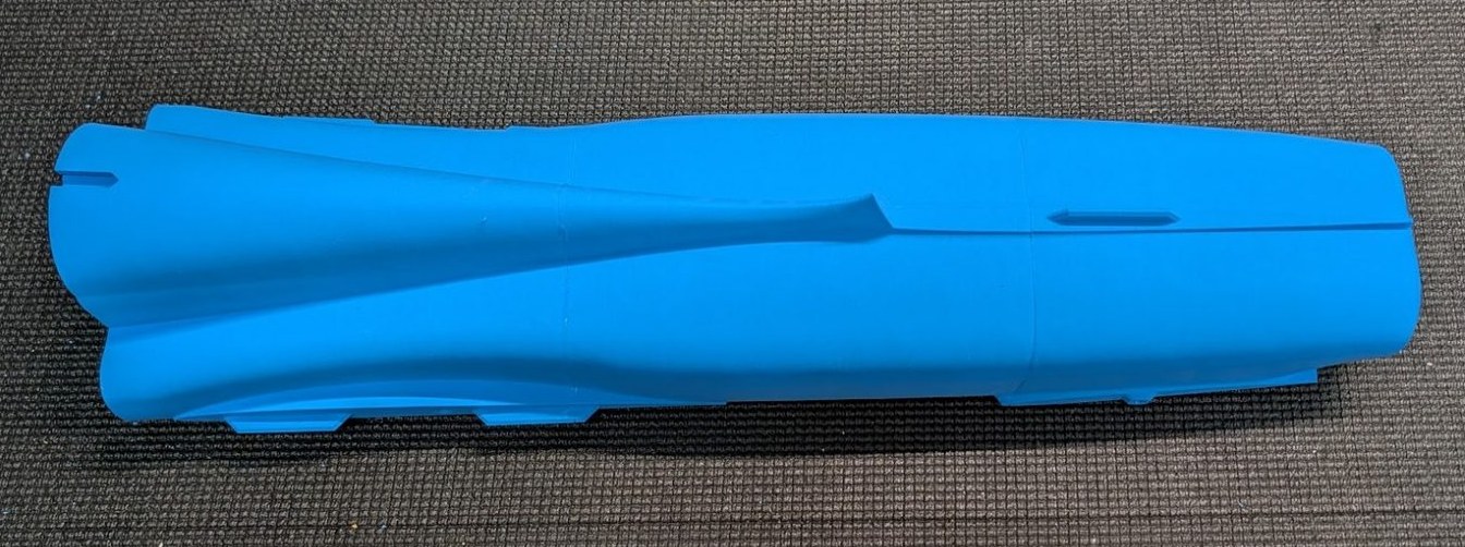
Using the same technique, join fuselage sections 4 and 5.
-
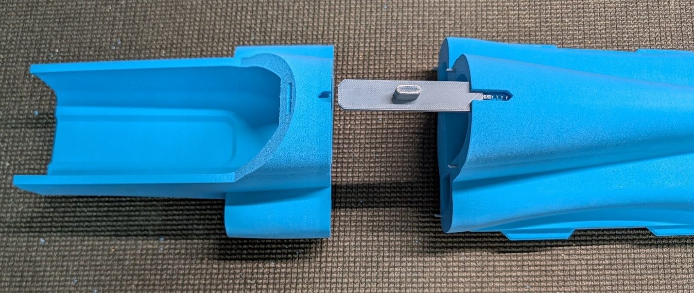
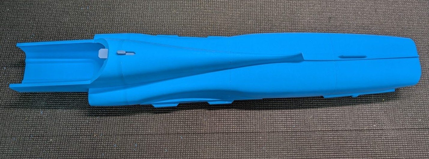
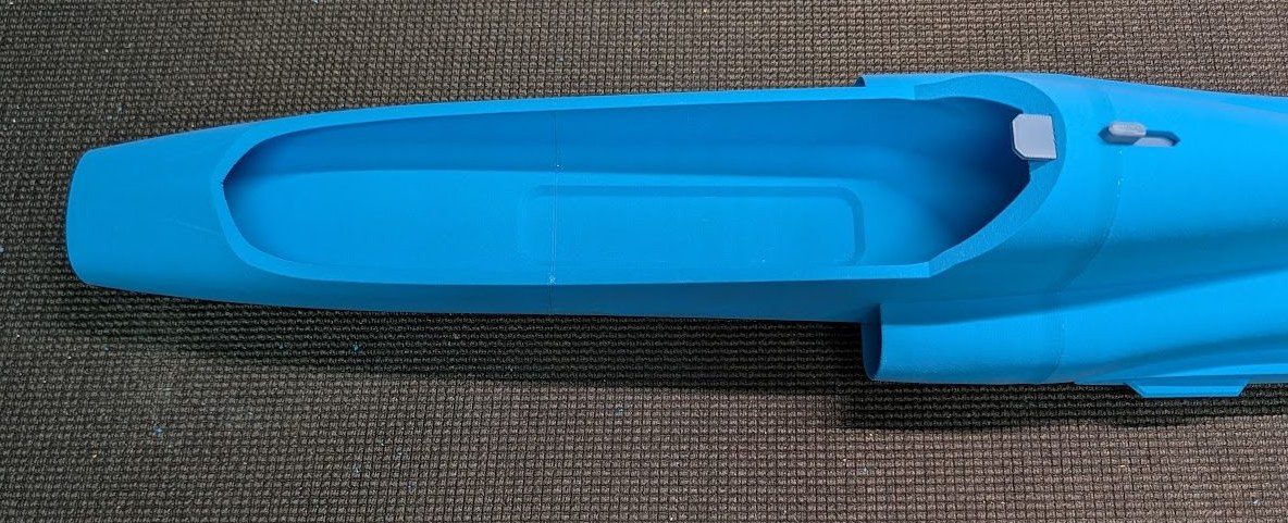
Place the hatch latch with a pen spring, then join fuselage 3 to the aft fuselage assembly.
-
Glue fuselage 2 to fuselage 3.
-
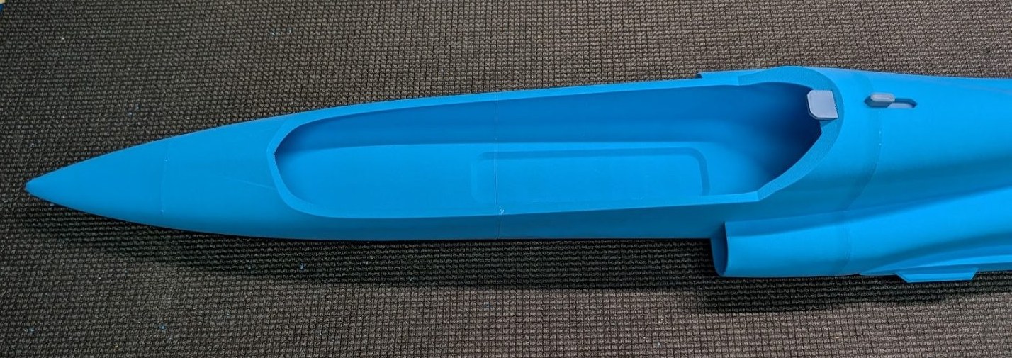
Add fuselage 1 to the nose of the assembly.
-
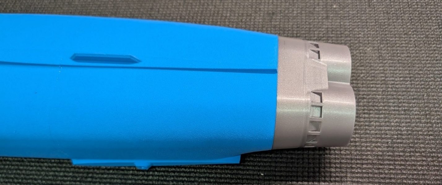
Attach the nozzle, again using pieces of filament to align.
-
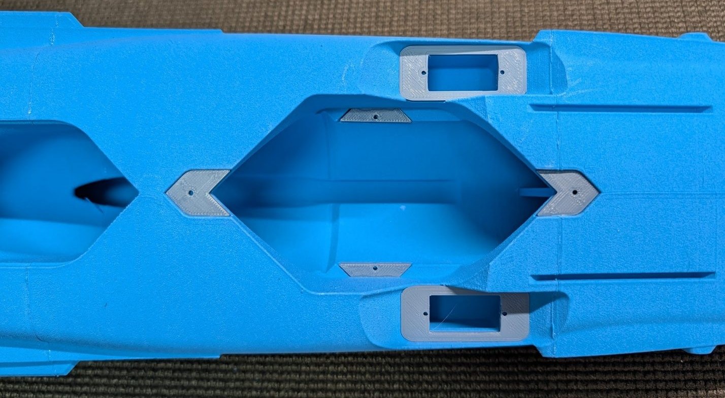
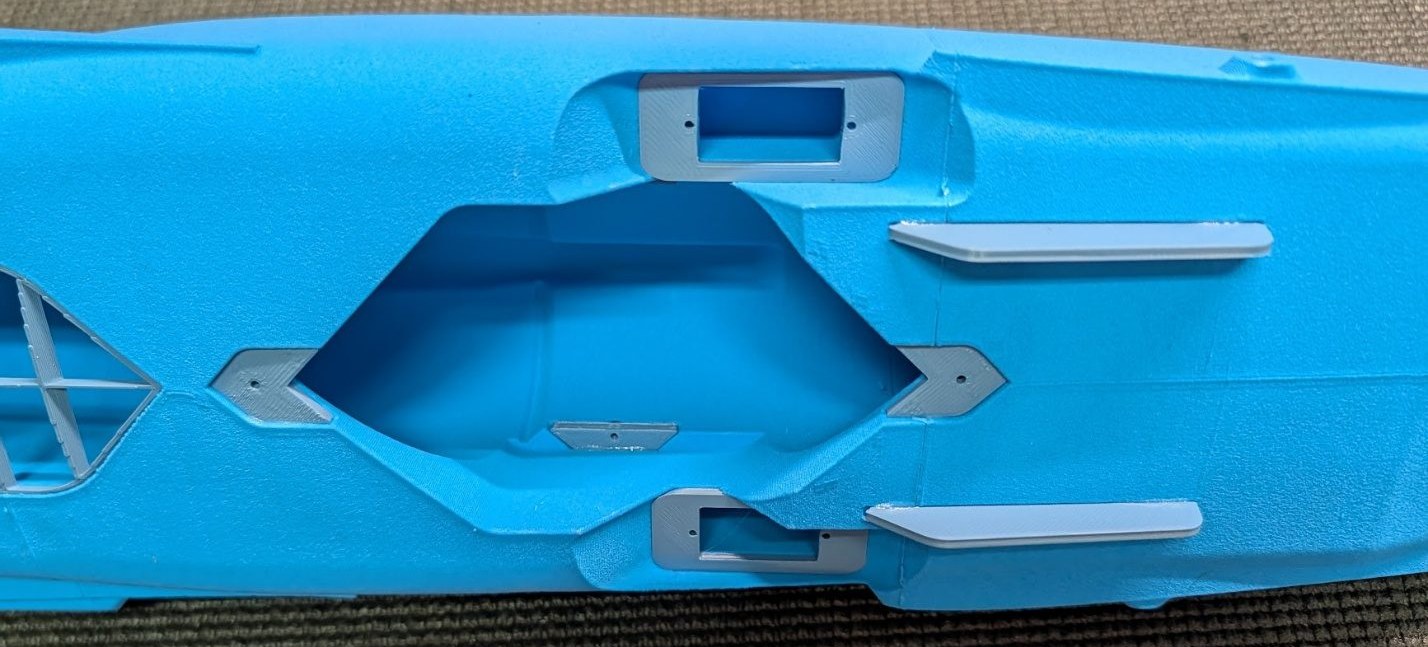
Prepare the fan area by gluing in the PLA fan mount and hatch mount tabs. Don't worry about orientation – they are symmetrical. Also glue in the servo mount plates.
-
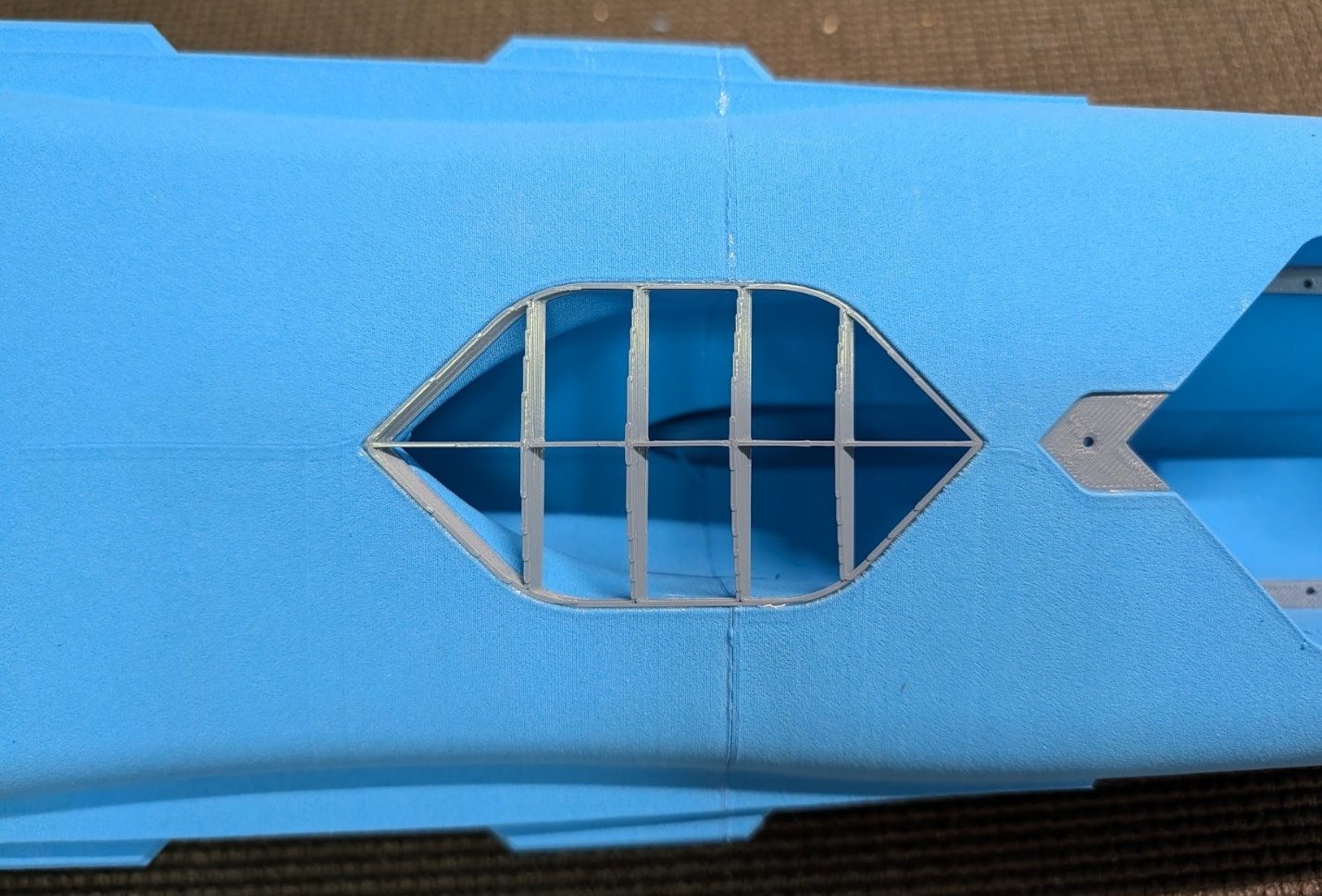
Glue the auxiliary inlet cover to the underside of the fuselage.
-
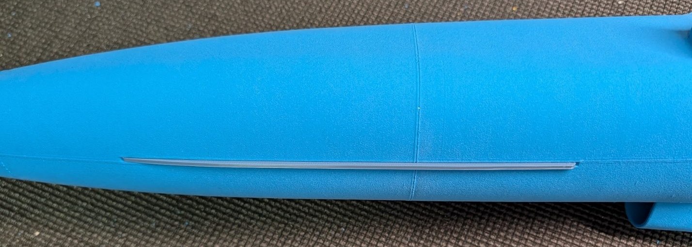
Attach the belly skid to the forward fuselage and the aft skids to the rear fuselage.
-
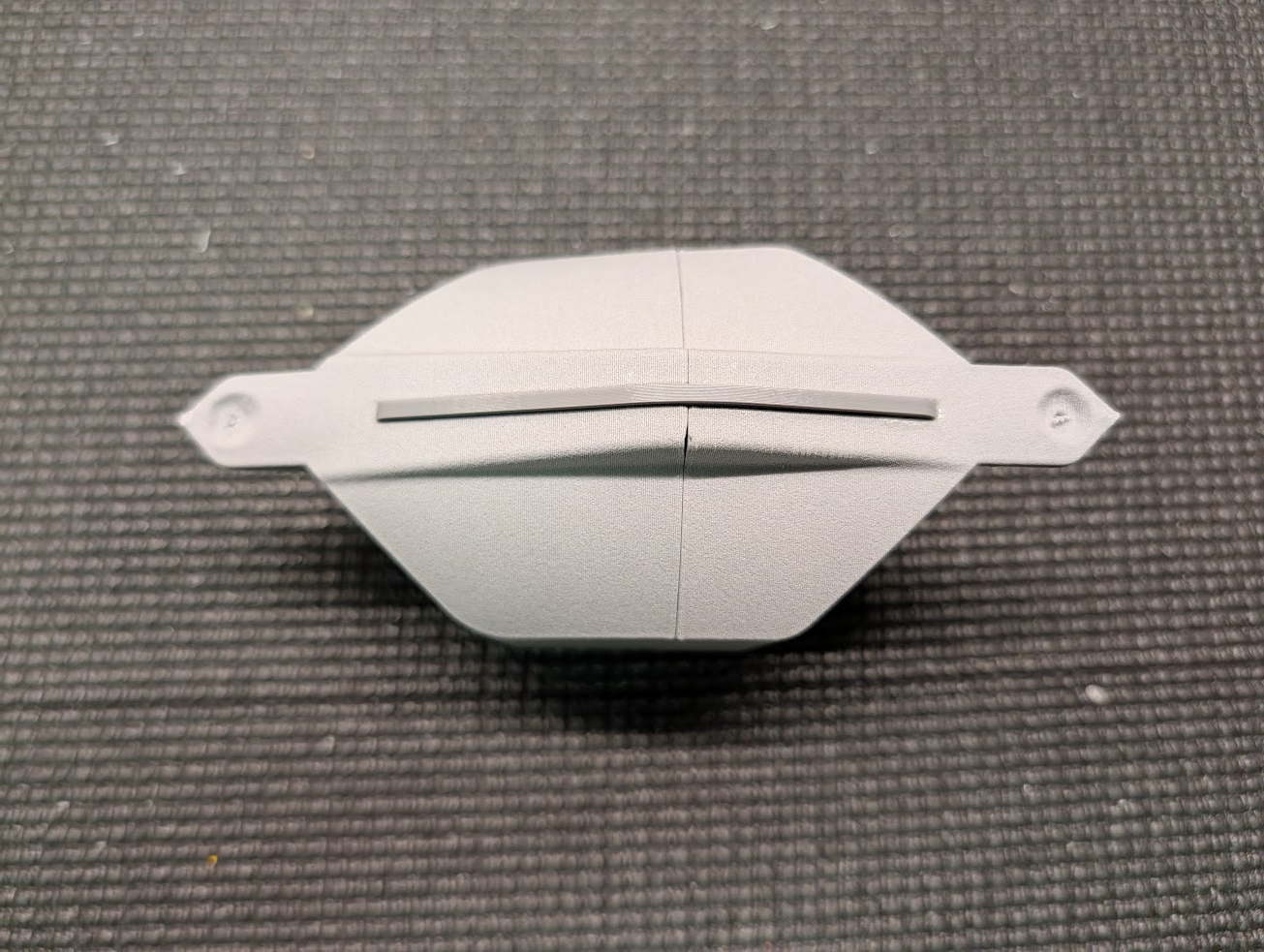
Join the two halves of the fan hatch cover.
-
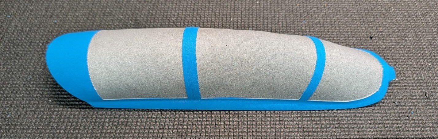
Join the two halves of the canopy.
-
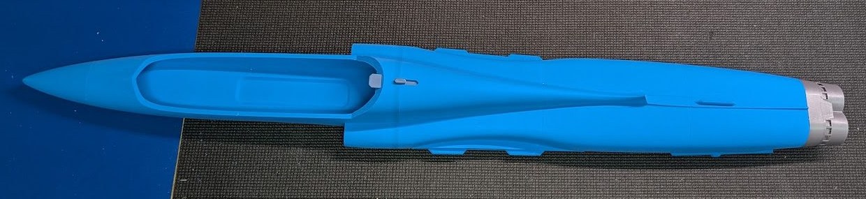
The fuselage assembly is now complete.
Control surface assembly
-
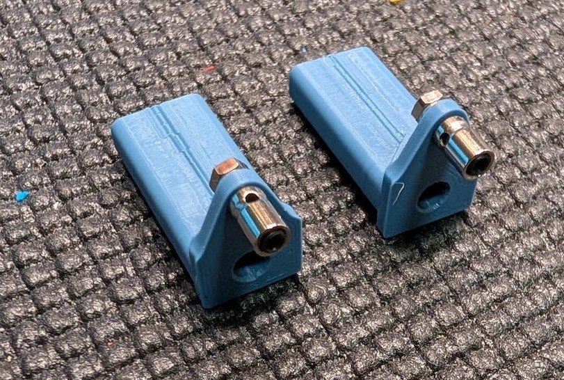
Prepare the stabilator pivot blocks by installing pushrod connectors as desired.
-
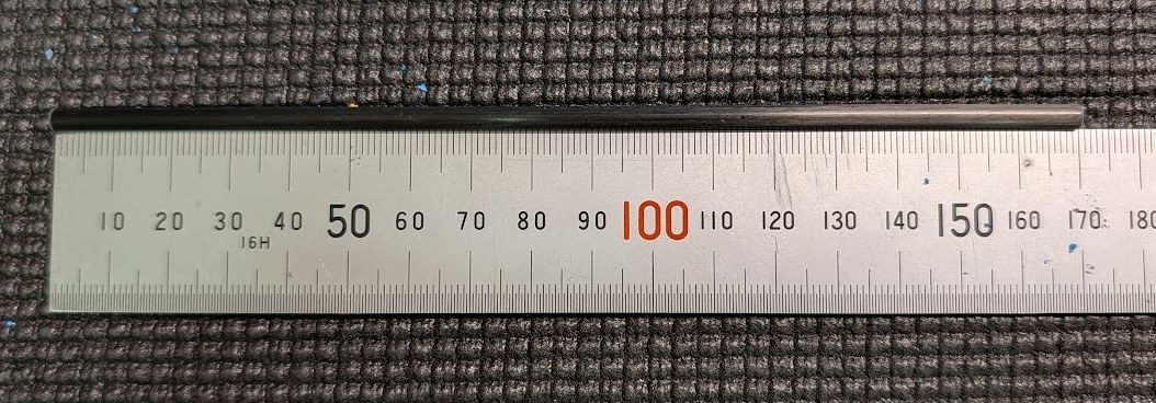
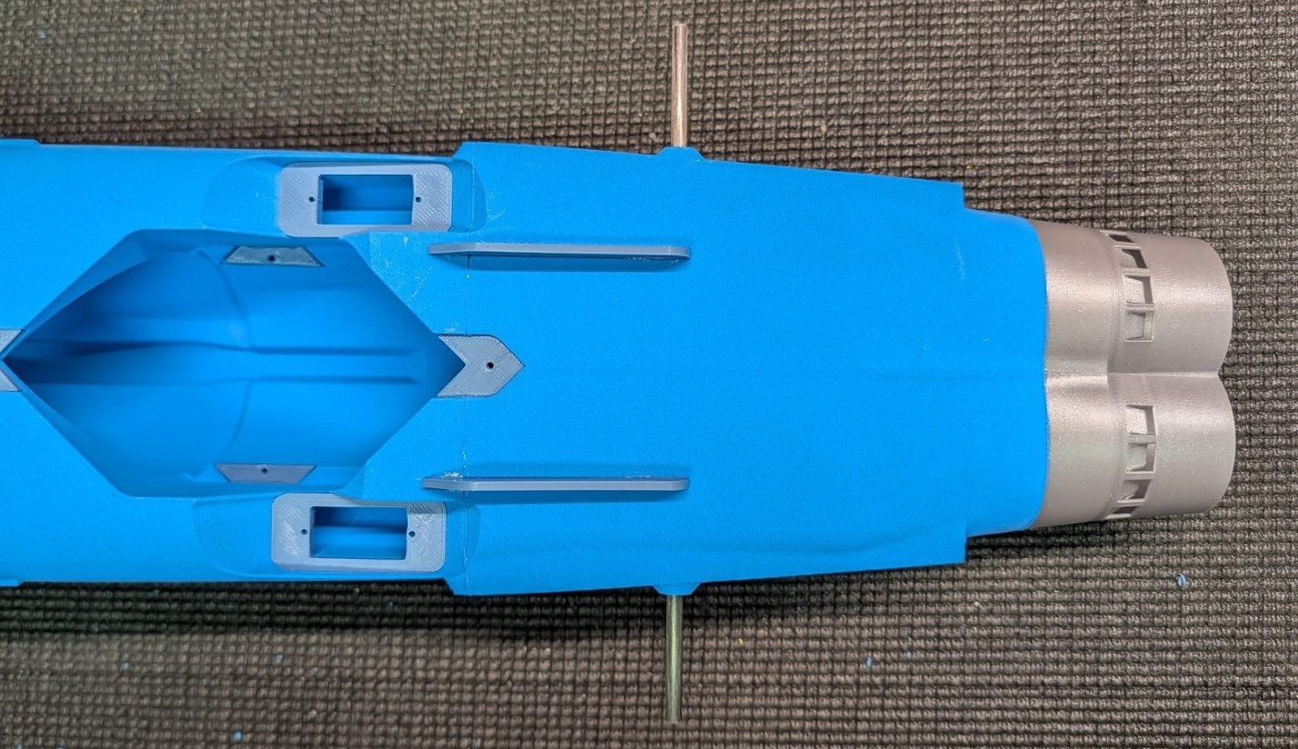
Cut the 4mm carbon fiber stabilator hinge tube to 170mm length.
-
Insert and center the stabilator hinge tube in the rear fuselage. Secure it with a few drops of CA, but be careful not to get any glue on the protruding ends.
-
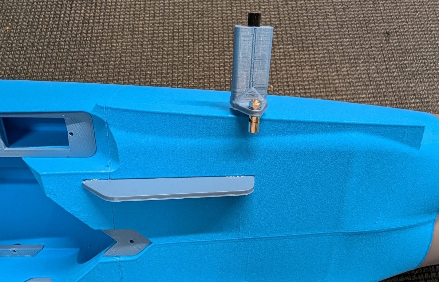
Slide the stabilator pivot blocks onto the ends of the tube.
-
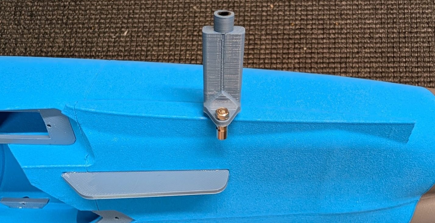
Glue the stabilator stoppers to the ends of the hinge tube. Ensure that the blocks can still move freely.
-
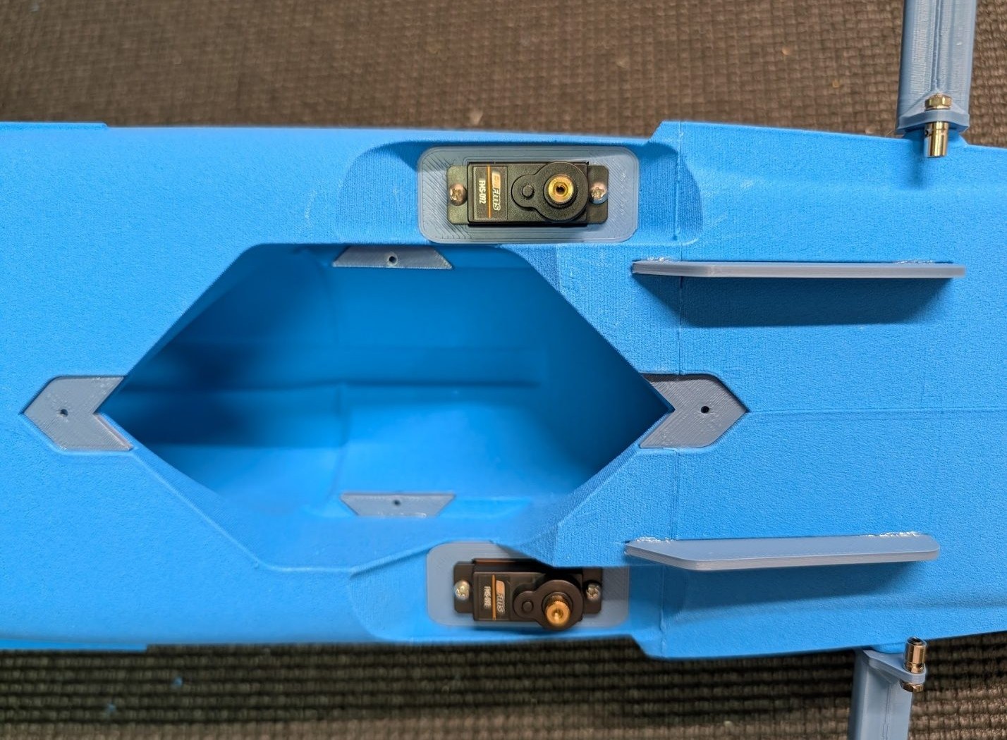
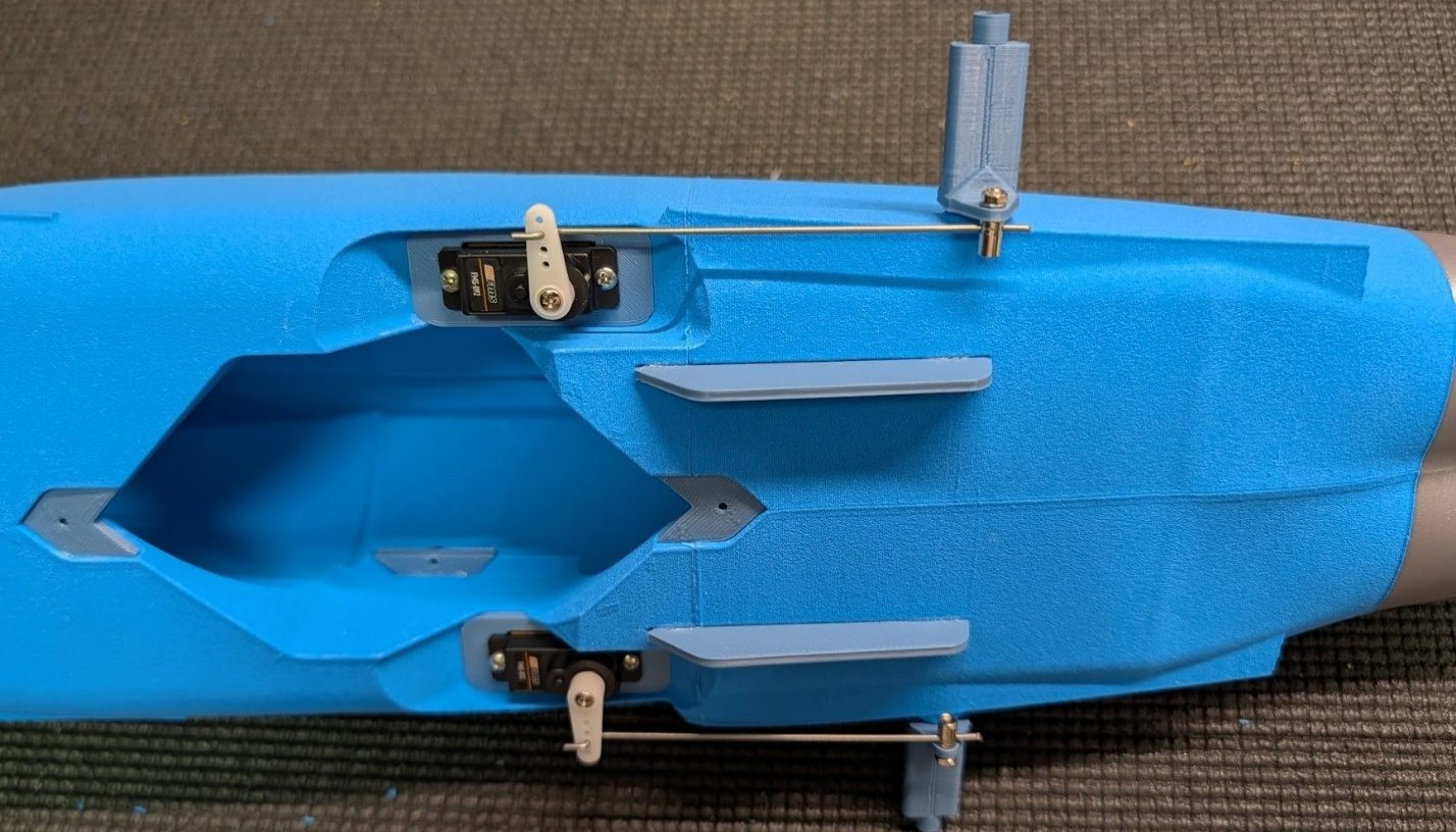
Center and install the servos using self-tapping screws.
-
Install pushrods into the servo arms and pivot blocks. Don't tighten them into position just yet.
-
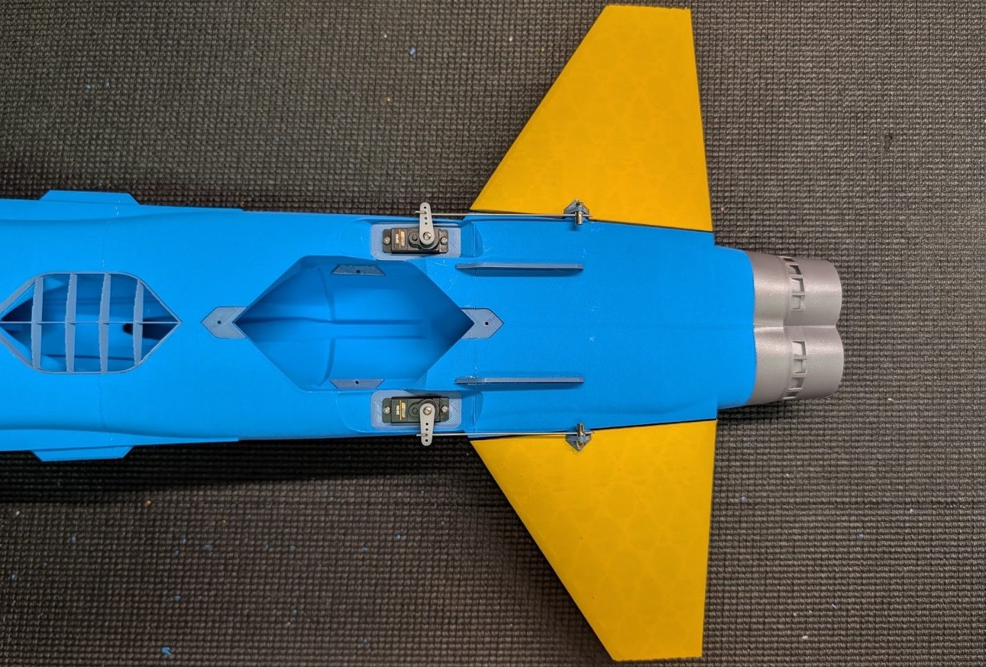
Glue the stabilators onto the pivot blocks and tighten the pushrods with the surfaces centered.
Final assembly
-
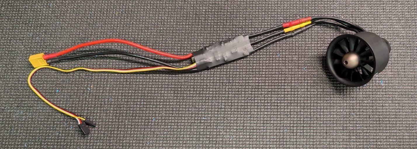
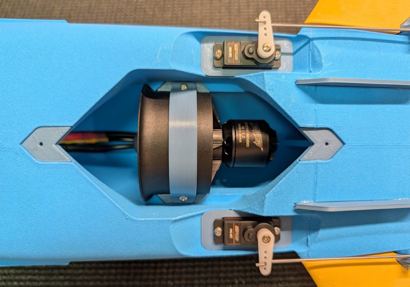
Prepare the fan and ESC. Test the fan to ensure it rotates in the correct direction before installing.
-
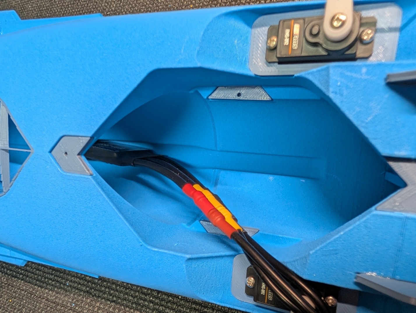
Feed the ESC and wiring into the channel within the fuselage. The ESC will slide quite far forward towards the canopy opening area.
-
Install the fan and secure it with two self-tapping screws. Make sure that the wiring rests securely in place under the fan. If your fan doesn't have mounting tabs, use the fan mount brace part to secure.
-
Install the fan hatch and secure it with two more self-tapping screws.

-
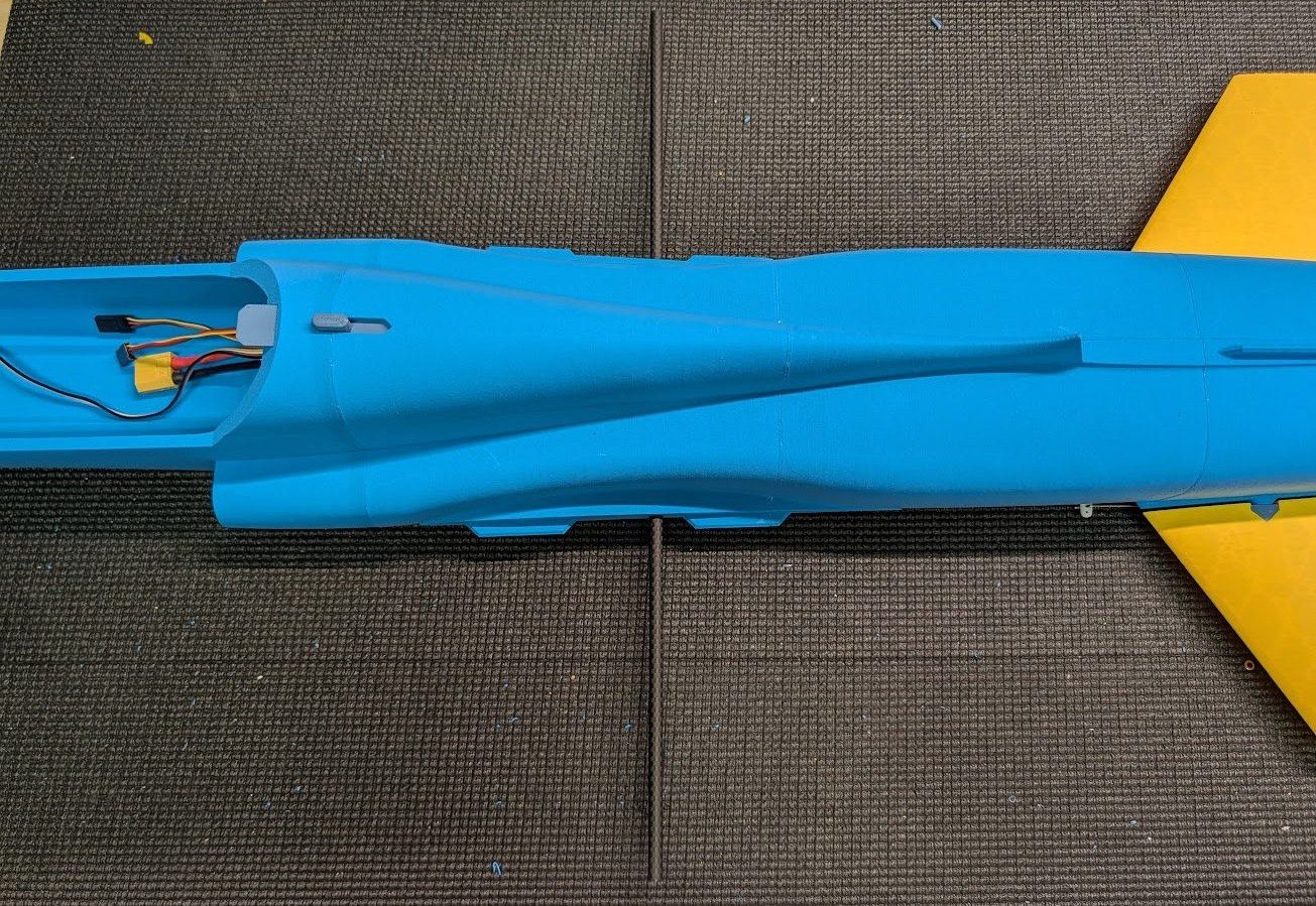
Slide the carbon wing tube into its slot in the fuselage. No need to glue it.
-
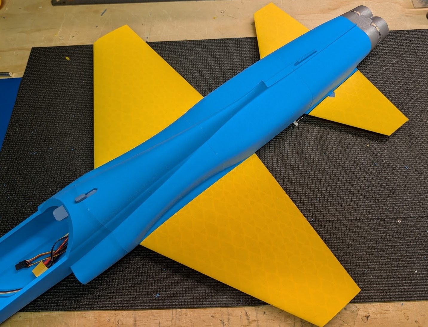
Glue the wings to the fuselage using the spars and alignment tabs as guidance.
-
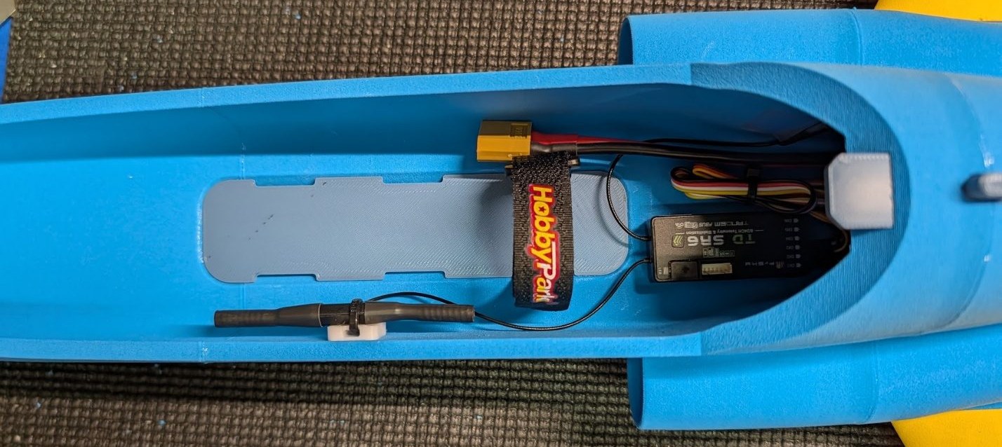
Glue the battery tray into the cabin area, with a Velcro strap in at least one of the slots. Arrange your receiver and battery as desired.
-
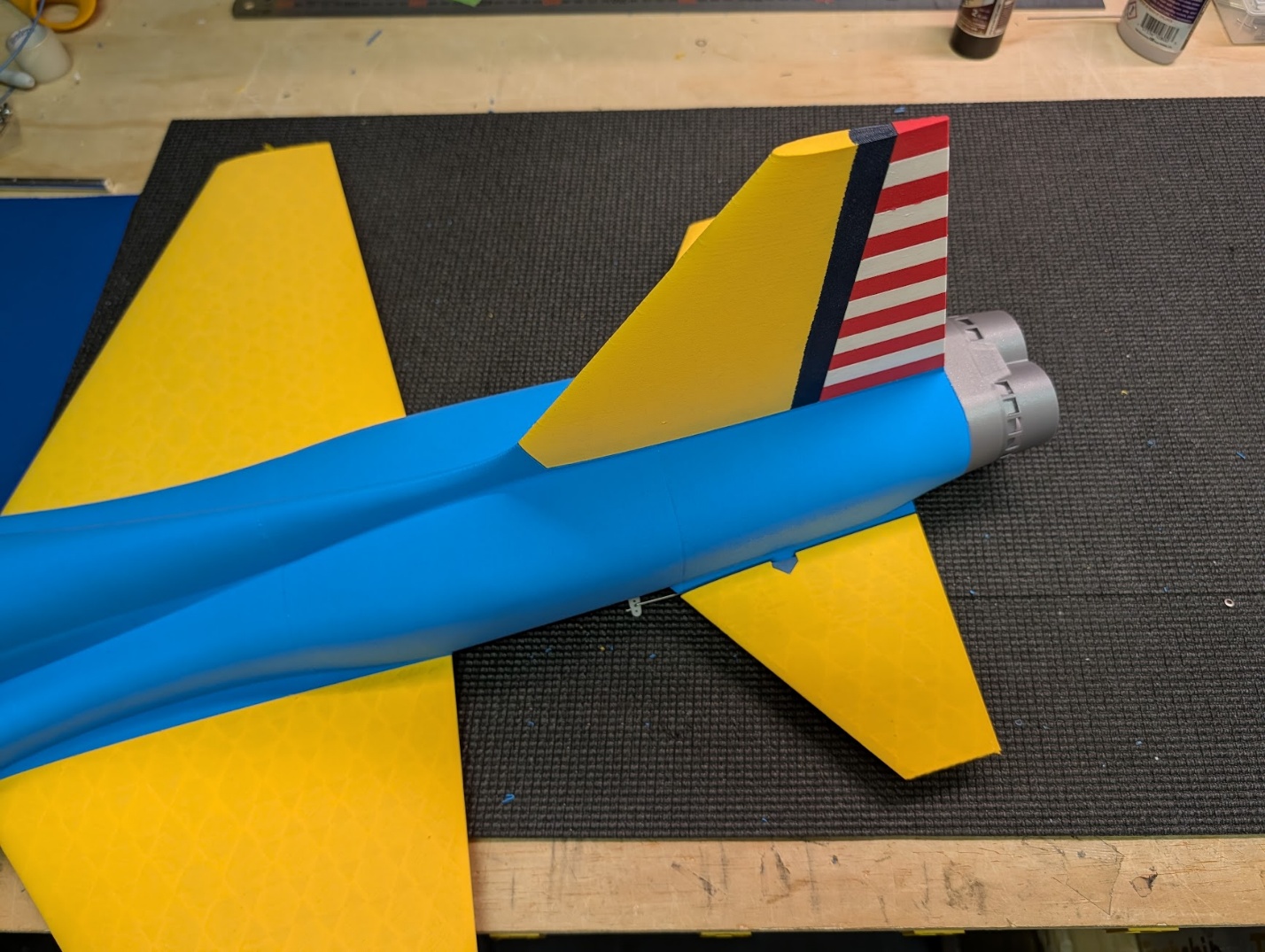
Now that the model doesn't need to be upside down anymore, it's a good time to glue on the vertical stabilizer. Assembly is complete!
Pre-flight setup
-
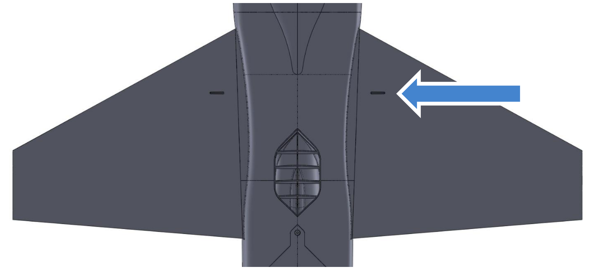
The recommended CG is marked with grooves on the underside of the wings.
-
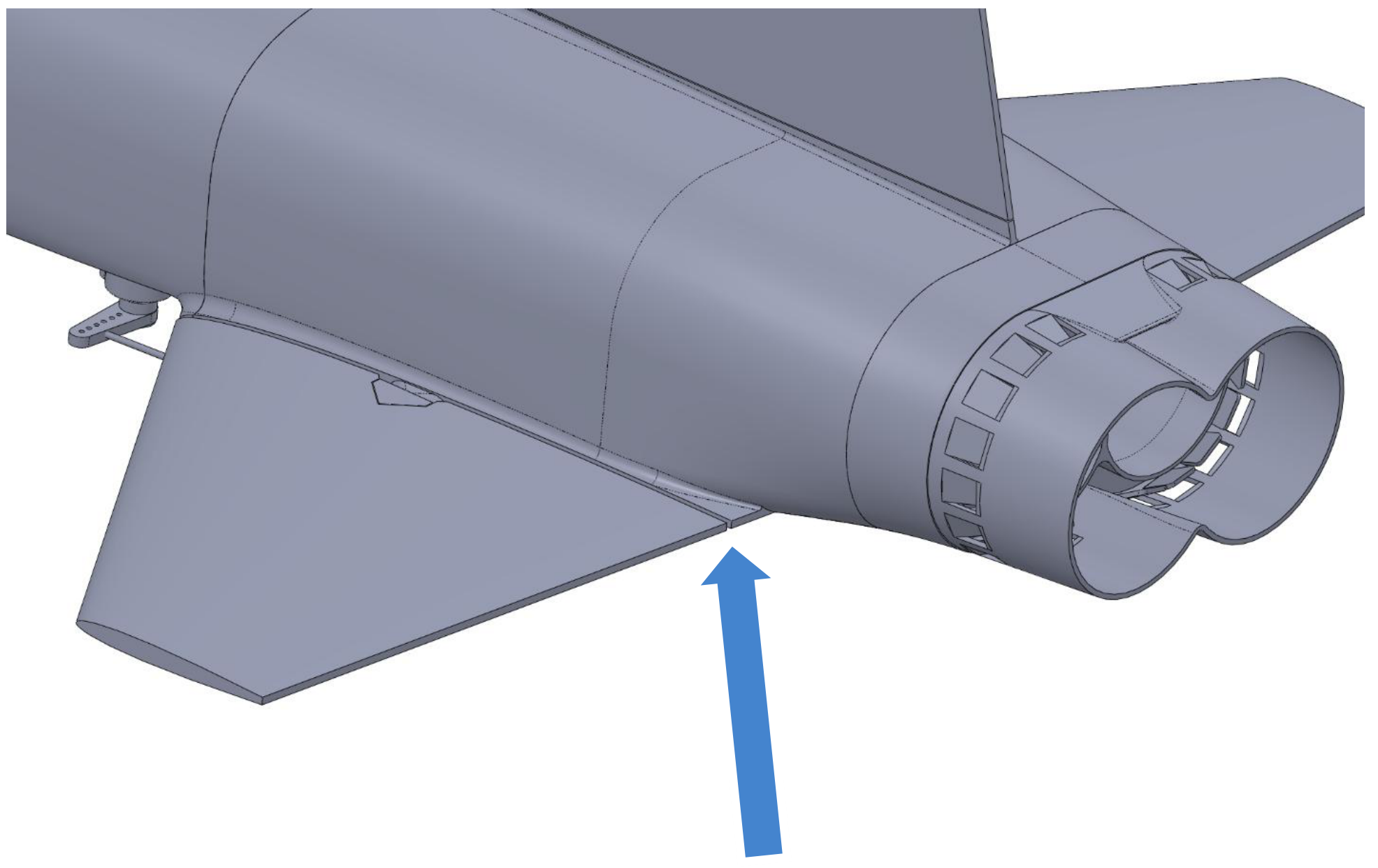
The neutral position for the stabilator aligns with the geometry of the aft fuselage.
-
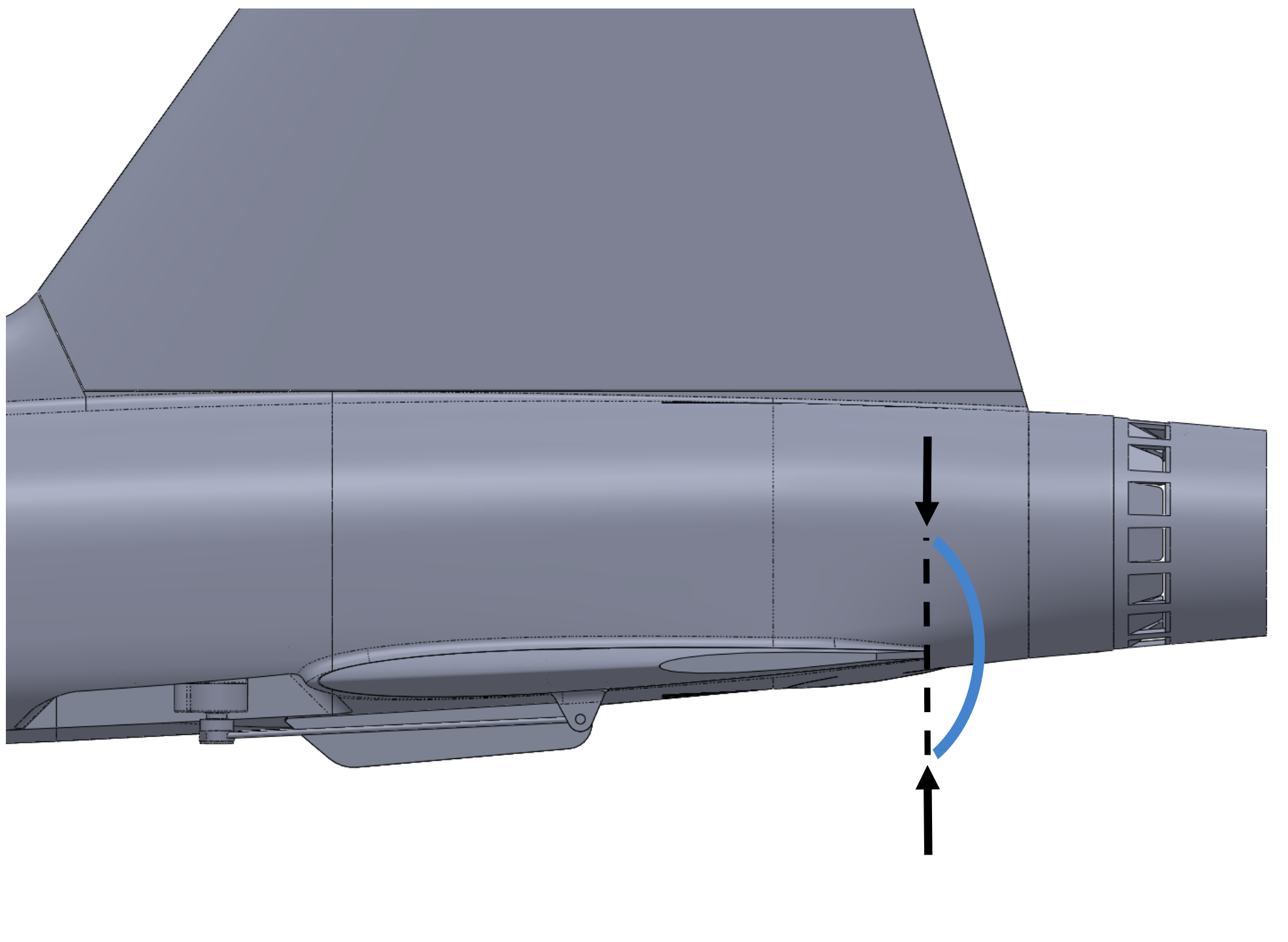
Adjust control deflections using the suggested throws below. These are measured at the trailing edge of the stabilators where they meet the fuselage. Dual rates are optional depending on your preferences.
Suggested control throws
| Flight Control | Travel | Exponential |
|---|---|---|
| Aileron | 15-20 mm up 15-20 mm down | 20-40% |
| Elevator | 15-20 mm up 10-15 mm down | 30-50% |
Congratulations - you're ready to fly!
Contact us
Have a question, issue, or just a cool idea for the next aircraft we should model? Drop us an email at: info@loftedaero.com